- 您現(xiàn)在的位置:買(mǎi)賣(mài)IC網(wǎng) > PDF目錄382381 > PCE84C487 (NXP Semiconductors N.V.) Microcontrollers for digital auto-sync and VST TV controller applications PDF資料下載
參數(shù)資料
| 型號(hào): | PCE84C487 |
| 廠商: | NXP Semiconductors N.V. |
| 英文描述: | Microcontrollers for digital auto-sync and VST TV controller applications |
| 中文描述: | 微控制器的數(shù)字自動(dòng)同步和VST電視控制器的應(yīng)用 |
| 文件頁(yè)數(shù): | 21/36頁(yè) |
| 文件大小: | 168K |
| 代理商: | PCE84C487 |
第1頁(yè)第2頁(yè)第3頁(yè)第4頁(yè)第5頁(yè)第6頁(yè)第7頁(yè)第8頁(yè)第9頁(yè)第10頁(yè)第11頁(yè)第12頁(yè)第13頁(yè)第14頁(yè)第15頁(yè)第16頁(yè)第17頁(yè)第18頁(yè)第19頁(yè)第20頁(yè)當(dāng)前第21頁(yè)第22頁(yè)第23頁(yè)第24頁(yè)第25頁(yè)第26頁(yè)第27頁(yè)第28頁(yè)第29頁(yè)第30頁(yè)第31頁(yè)第32頁(yè)第33頁(yè)第34頁(yè)第35頁(yè)第36頁(yè)

1996 Feb 21
21
Philips Semiconductors
Objective specification
Microcontrollers for digital auto-sync and
VST TV controller applications
PCE84C486; PCE84C487
9
I
2
C-BUS INTERFACE
The PCE84C48X has an on-chip I
2
C-bus interface that
can be used in master or slave mode. Full details of the
I
2
C-bus are given in the document “The I
2
C-bus and how
to use it” This document may be ordered using the code
9398 393 40011.
The I
2
C-bus interface lines SDA and SCL share the same
pins as port lines DP20 and P10 respectively. Selection of
the pin function as either an I
2
C-bus line or a port line is
achieved using the SDAE and SCLE bits in Derivative
Register 22. Only port Option 2 is available for both of
these pins.
10 8-BIT COUNTER (T3)
The main application for this counter is in the frequency
measurement of the Hsync signal.
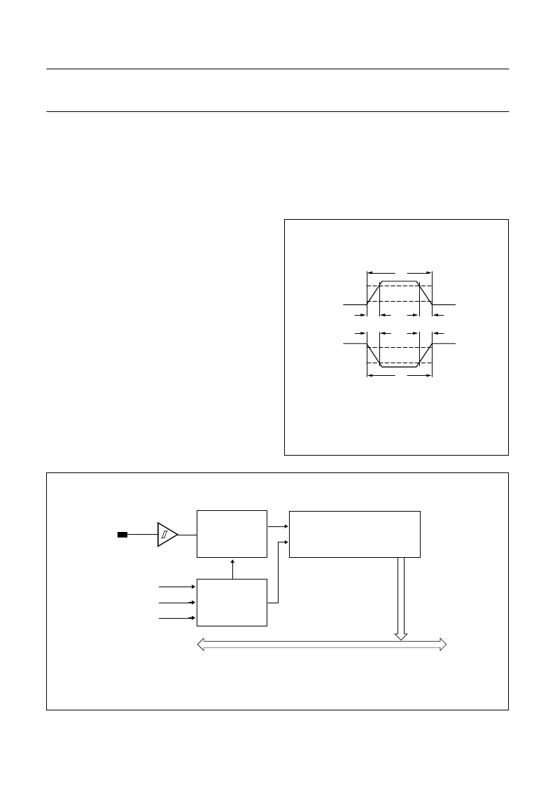
The block diagram of the 8-bit counter is shown in Fig.22.
A Schmitt trigger is used at the input for noise rejection and
also to shape the input signal into a square wave. The T3
input is sampled at a frequency of
1
3
×
f
osc
by the sample
clock which synchronizes the internal T3 clock and the
read operation of Derivative Register 24. The rising edge
of the input increments the ripple counter by 1.
The contents of T3 may be read using the instruction
MOV A, D24H. As soon as the data is read, the counter is
reset to zero. A counter overflow or Power-on-reset also
resets the counter contents to zero.
If the rising and falling edges of the input pulse are less
than 30 ns then the minimum pulse width that the T3 input
will recognise is 3/f
osc
+ 100 ns. If the system clock is
10 MHz then the minimum pulse width is 400 ns. In some
display modes, the active pulse width of the Hsync signal
can be less than 400 ns; in this situation some external
application circuitry may be required.
handbook, halfpage
tH
tL
0.9 VDD
0.1 VDD
0.1 VDD
0.9 VDD
tr
tr
tf
MGC719
tf
Fig.18 T3 input waveform.
Fig.19 Block diagram of the 8-bit counter (T3).
handbook, full pagewidth
MGC717
T3
Power-on-reset
sample clock
READ D24H
EMU
8-BIT COUNTER
RESET
Q0 to Q7
CK
Data bus
SYNCHRONISATION
CIRCUIT
T3 COUNTER
CONTROL CIRCUIT
相關(guān)PDF資料 |
PDF描述 |
|---|---|
| PCE84C886 | Microcontroller for monitor OSD and auto-sync applications |
| PCF1000 | Analog IC |
| PCF600 | Analog IC |
| PCF1174C | 4-digit static LCD car clock |
| PCF1174CT | 4-digit static LCD car clock |
相關(guān)代理商/技術(shù)參數(shù) |
參數(shù)描述 |
|---|---|
| PCE84C882 | 制造商:PHILIPS 制造商全稱(chēng):NXP Semiconductors 功能描述:Microcontroller for monitor OSD and auto-sync applications |
| PCE84C886 | 制造商:PHILIPS 制造商全稱(chēng):NXP Semiconductors 功能描述:Microcontroller for monitor OSD and auto-sync applications |
| PCEA02 | 制造商:ADAM-TECH 制造商全稱(chēng):Adam Technologies, Inc. 功能描述:.100&.156 RECEPTACLE WITH BOARD HOOKS |
| PCE-A-05 | 制造商:ADAM-TECH 制造商全稱(chēng):Adam Technologies, Inc. 功能描述:.100 RECEPTACLE WITH BOARD HOOKS |
| PCEA10 | 制造商:ADAM-TECH 制造商全稱(chēng):Adam Technologies, Inc. 功能描述:.100&.156 RECEPTACLE WITH BOARD HOOKS |
發(fā)布緊急采購(gòu),3分鐘左右您將得到回復(fù)。