- 您現(xiàn)在的位置:買賣IC網(wǎng) > PDF目錄384801 > OX16C954-PCC60-B (Electronic Theatre Controls, Inc.) High Performance Quad UART with 128-byte FIFOs Intel / Motorola Bus Interface PDF資料下載
參數(shù)資料
| 型號: | OX16C954-PCC60-B |
| 廠商: | Electronic Theatre Controls, Inc. |
| 英文描述: | High Performance Quad UART with 128-byte FIFOs Intel / Motorola Bus Interface |
| 中文描述: | UART的高性能四路128字節(jié)的FIFO英特爾/摩托羅拉總線接口 |
| 文件頁數(shù): | 15/54頁 |
| 文件大小: | 529K |
| 代理商: | OX16C954-PCC60-B |
第1頁第2頁第3頁第4頁第5頁第6頁第7頁第8頁第9頁第10頁第11頁第12頁第13頁第14頁當(dāng)前第15頁第16頁第17頁第18頁第19頁第20頁第21頁第22頁第23頁第24頁第25頁第26頁第27頁第28頁第29頁第30頁第31頁第32頁第33頁第34頁第35頁第36頁第37頁第38頁第39頁第40頁第41頁第42頁第43頁第44頁第45頁第46頁第47頁第48頁第49頁第50頁第51頁第52頁第53頁第54頁
Data Sheet Revision 1.0
Page 15
OX16C954 rev B
OXFORD SEMICONDUCTOR LTD.
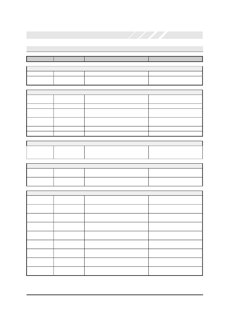
4.1
Pin
Further Pin Information
Description
Action when used
Action when not used
Intel Mode Bus Interface Pins
I/M#
CS0#-CS3#
Intel / Motorola Mode Tie high for Intel style bus mode
Chip selects
Connect direct to active low channel select
signals for UART channels 0-3 respectively
Leave unconnected (Internal pull-up)
n/a
Motorola Mode Bus Interface Pins
I/M#
Intel / Motorola Mode Tie low for Motorola style bus mode
n/a
Must be tied low for Motorola mode
n/a
n/a
DS#(CS0#)
A3-4 (CS1-2#)
Data Strobe
Additional
lines
Global interrupt
Connect direct to data strobe generator logic
Connect direct to channel selection logic
A[4:3] = 00 = ch. 1, 01 = ch. 2 etc.
Interrupt for all channels. Connect to an
available processor interrupt line
n/a
n/a
address
Leave unconnected
(Interrupts can not be used)
Tie high
Leave unconnected
IRQ#(INT0)
CS3#
INT1-3
Unused
Unused
Control Pins
INTSEL
Interrupt Control
Mode (used in Intel
mode only)
Tie high to keep the interrupt pins
permanently enabled.
Tie low or leave unconnected to allow
software enable/disable of the
interrupt pin.
DMA Pins
RXRDY#
DMA Control signal
output
DMA Control signal
output
Connect direct to DMA control circuitry
Leave unconnected
TXRDY#
Connect direct to DMA control circuitry
Leave unconnected
Common Channel Pins
Connect to a suitable line driver
Connect to a suitable line receiver
Connect to a suitable line driver
Connect to a suitable line receiver
Connect to a suitable line driver
Connect to a suitable line receiver
Connect to a suitable line receiver
Connect to a suitable line receiver
Connect to an available processor interrupt
line
SOUT
Serial data output
Leave unconnected
(Serial data can not be transmtted)
Leave unconnected
(Serial data can not be received)
Leave unconnected
SIN
Serial data input
RTS#
Request-To-Send
Modemsignal output
Clear-To-Send
Modemsignal input
Data-Termnal-Ready
Modemsignal output
Data-Set-Ready
Modemsignal input
Data-Carrier-Detect
Modemsignal input
Ring-Indicator
Modemsignal input
Interrupt Output
CTS#
Tie high
DTR#
Leave unconnected
DSR#
Tie high
DCD#
Tie high
RI#
Tie high
INT
Leave unconnected
(Interrupts can not be used)
相關(guān)PDF資料 |
PDF描述 |
|---|---|
| OX16C954-TQC60-B | High Performance Quad UART with 128-byte FIFOs Intel / Motorola Bus Interface |
| OX16CF950 | LOW COST ASYNCHRONOUS 16 BIT CARD |
| OX2000A | OCXO |
| OX2020A | OCXO |
| OX2420A | OCXO |
相關(guān)代理商/技術(shù)參數(shù) |
參數(shù)描述 |
|---|---|
| OX16C954-PLBG | 制造商:Oxford Semiconductor 功能描述:IC UART 4CH SMD PLCC68 954 |
| OX16C954-TQBG | 功能描述:外圍驅(qū)動器與原件 - PCI High performance quad UART RoHS:否 制造商:PLX Technology 工作電源電壓: 最大工作溫度: 安裝風(fēng)格:SMD/SMT 封裝 / 箱體:FCBGA-1156 封裝:Tray |
| OX16C954-TQC60-B | 制造商:未知廠家 制造商全稱:未知廠家 功能描述:High Performance Quad UART with 128-byte FIFOs Intel / Motorola Bus Interface |
| OX16C95X | 制造商:OXFORD 制造商全稱:OXFORD 功能描述:HIGH-PERFORMANCE UART FAMILY REFERENCE DRIVERS |
| OX16CB950 | 制造商:OXFORD 制造商全稱:OXFORD 功能描述:Intelligent UART with 3.3v PCI/Cardbus Interface |
發(fā)布緊急采購,3分鐘左右您將得到回復(fù)。