- 您現(xiàn)在的位置:買賣IC網(wǎng) > Datasheet目錄45 > NCP1927DR2G (ON Semiconductor)IC CTLR PFC/FLYBACK 16-SOIC Datasheet資料下載
參數(shù)資料
| 型號(hào): | NCP1927DR2G |
| 廠商: | ON Semiconductor |
| 文件頁數(shù): | 13/24頁 |
| 文件大小: | 531K |
| 描述: | IC CTLR PFC/FLYBACK 16-SOIC |
| 標(biāo)準(zhǔn)包裝: | 2,500 |
| 系列: | * |
NCP1927
http://onsemi.com
13
ShortWinding Protection
Under some conditions, like a transformer winding or
output diode shortcircuit, the primary current increases
above V
ILIM
before the LEB timer expires. To prevent
dangerously high current from flowing, an additional
comparator senses when V
FCS
reaches V
CS(stop)
. Once this
comparator toggles, the controller immediately latches off.
The effect of latching off the IC is identical to shutdown
mode, however, the V
CC
cycle repeats indefinitely until the
input power is removed and C
VCC
is allowed to discharge
below V
CC(reset)
. When input power is reapplied, the
NCP1927 operates according to the initial poweron
sequence. The V
CC
behavior during short winding
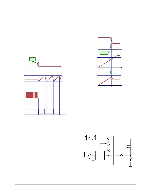
protection is shown in Figure 9.
Figure 9. V
CC
Behavior During Short Winding
Protection
time
FCS Pin
time
V
CC
time
DRV
V
CC(on)
V
CC(off)
Short
Winding
Detected
V
CS(stop)
time
I
CC
I
CC4
ICC6
I
CC2
Feedback
The ratio from the feedback voltage to the current limit
threshold, K
FFB
(typically 5), determines the peak current
limit threshold. This means that the feedback voltage when
the current limit threshold equals V
ILIM
is 3.5 V (typical).
The FFB pin is connected to the internal V
DD
rail through
a resistor divider. To ease system design, the FFB pin is
represented by a Thevenin equivalent circuit containing a
voltage source and series resistor, V
FFB(open)
(typically 5 V)
and R
FFB
(typically 20 kW).
SoftStart
The NCP1927 flyback controller features an internal
softstart circuit. Every time the controller starts (i.e. the
controller was off and starts, or restarts due to a fault), a
softstart is applied when V
CC
reaches V
CC(on)
. The current
limit threshold is linearly increased from 0 until it reaches
V
ILIM
(in 4.0 ms), or until the feedback loop imposes a
setpoint lower than the one imposed by the softstart (the 2
comparator outputs are ORed together). Figure 10 shows a
typical startup sequence.
Figure 10. SoftStart Timing
Time
VFB
Time
Softstart ramp
V
ILIM
t
SSTART
Time
CS Setpoint
V
ILIM
VFB takes
over softstart
Ramp Compensation
Ramp compensation is a known method for preventing
subharmonic oscillations. These oscillations take place at
half the switching frequency and occur only during
continuous conduction mode (CCM) when the duty ratio is
greater than 50%. To prevent these oscillations, one
typically lowers the current loop gain by injecting between
50% and 75% of the inductor downslope. This is done by
inserting a resistor (R
SCOMP
) between the FCS pin and the
current sense resistor. Figure 11 shows an example of this.
The ramp signal is disconnected from the FCS pin during the
off time.
Figure 11. Inserting a Resistor
+
ON
L.E.B.
FDRV
Reset
from FFB Setpoint
FCS
R
SCOMP
I
ramp
I
ramp(MAX)
R
sense
0 mA
相關(guān)PDF資料 |
PDF描述 |
|---|---|
| NCP380HMU21AATBG | IC CURRENT LIMIT SWITCH 6-UDFN |
| NCT1008DMT3R2G | TMP DIO MON/SMBUS 4CH 8WDFN |
| NCT210RQR2G | IC TEMP SENSOR LOC/REM 16QSOP |
| NCT214MT3R2G | IC TEMP SENSOR LOC/REM 10WDFN |
| NCT72CMNR2G | IC REMOTE THERMAL SENSOR 8-DFN |
相關(guān)代理商/技術(shù)參數(shù) |
參數(shù)描述 |
|---|---|
| NCP1937A1DR2G | 制造商:ON Semiconductor 功能描述:COMBO PFC & QUAZI FLYBACK - Tape and Reel 制造商:ON Semiconductor 功能描述:REEL / COMBO PFC & QUAZI FLYBACK |
| NCP1937B1DR2G | 制造商:ON Semiconductor 功能描述:COMBO PFC & QUAZI FLYBACK - Tape and Reel |
| NCP1937BADAPGEVB | 制造商:ON Semiconductor 功能描述:ADPTR 90W PFC+QR<10MW - Bulk 制造商:ON Semiconductor 功能描述:BOARD EVAL FOR NCP1937 制造商:ON Semiconductor 功能描述:Power Management IC Development Tools 90 W Adapter PFC+QR 10 MW Eval Brd |
| NCP21WB333 | 制造商:MURATA 制造商全稱:Murata Manufacturing Co., Ltd. 功能描述:for Surface Mounting Application |
| NCP21WB333J03RA | 功能描述:熱敏電阻 - NTC 33K OHM 5% RoHS:否 制造商:EPCOS 電阻:10 kOhms 功率額定值:150 mW 容差:2 % 端接類型:Radial 系列:B57703M 工作溫度范圍:- 55 C to + 125 C |
發(fā)布緊急采購,3分鐘左右您將得到回復(fù)。