- 您現(xiàn)在的位置:買(mǎi)賣(mài)IC網(wǎng) > PDF目錄371145 > MRF6408 (MOTOROLA INC) XC17S10VOG8C PDF資料下載
參數(shù)資料
| 型號(hào): | MRF6408 |
| 廠商: | MOTOROLA INC |
| 元件分類(lèi): | 功率晶體管 |
| 英文描述: | XC17S10VOG8C |
| 中文描述: | L BAND, Si, NPN, RF POWER TRANSISTOR |
| 文件頁(yè)數(shù): | 1/8頁(yè) |
| 文件大小: | 230K |
| 代理商: | MRF6408 |
1
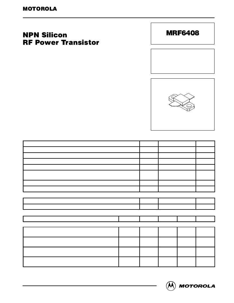
MRF6408
MOTOROLA RF DEVICE DATA
Motorola, Inc. 1997
The RF Line
Designed for PCN and PCS base station applications, the MRF6408
incorporates high value emitter ballast resistors, gold metallizations and offers
a high degree of reliability and ruggedness.
To be used in class AB for PCN–PCS / Cellular Radio
Specified 26 Volts, 1.88 GHz Characteristics
Output Power = 12 Watts CW
Typical Gain = 8.8 dB
Typical Efficiency = 42%
Specified 26 Volts, 1.99 GHz Characteristics
Output Power = 12 Watts CW
Typical Gain = 8.3 dB
Typical Efficiency = 39%
Circuit Board Photomaster Available by Ordering Document
MRF6408PHT/D from Motorola Literature Distribution.
MAXIMUM RATINGS
Rating
Symbol
Value
Unit
Collector–Emitter Voltage
VCEO
VCES
VEBO
IC
PD
24
Vdc
Collector–Emitter Voltage
60
Vdc
Emitter–Base Voltage
4
Vdc
Collector–Current — Continuous
5
Adc
Total Device Dissipation @ TC = 25
°
C
Derate above 25
°
C
60
0.35
Watts
W/
°
C
Storage Temperature Range
Tstg
TJ
–65 to +150
°
C
Operating Junction Temperature
200
°
C
THERMAL CHARACTERISTICS
Characteristic
Symbol
Max
Unit
Thermal Resistance, Junction to Case (1)
R
θ
JC
2.8
°
C/W
ELECTRICAL CHARACTERISTICS
(TC = 25
°
C unless otherwise noted)
Characteristic
Symbol
Min
Typ
Max
Unit
OFF CHARACTERISTICS
Collector–Emitter Breakdown Voltage
(IC = 20 mAdc, IB = 0)
V(BR)CEO
24
30
—
Vdc
Emitter–Base Breakdown Voltage
(IB = 5.0 mAdc, IC = 0)
V(BR)EBO
4
5
—
Vdc
Collector–Emitter Breakdown Voltage
(IC = 20 mAdc, VBE = 0)
V(BR)CES
55
64
—
Vdc
Collector Cutoff Current
(VCE = 30 Vdc, VBE = 0)
ICES
—
—
6
mA
(1) Thermal resistance is determined under specified RF operating condition.
Order this document
by MRF6408/D
SEMICONDUCTOR TECHNICAL DATA
12 W, 2.0 GHz
RF POWER TRANSISTOR
NPN SILICON
CASE 395C–01, STYLE 1
REV 2
相關(guān)PDF資料 |
PDF描述 |
|---|---|
| MRF6409 | NPN Silicon RF Power Transistor(NPN硅射頻功率晶體管) |
| MRF6414PHT | 14 pin DIP, 5.0 Volt, HCMOS/TTL, Clock Oscillator |
| MRF641 | RF POWER TRANSISTOR NPN SILICON |
| MRF644 | RF POWER TRANSISTOR NPN SILICON |
| MRF650 | RF POWER TRANSISTOR NPN SILICON |
相關(guān)代理商/技術(shù)參數(shù) |
參數(shù)描述 |
|---|---|
| MRF6409 | 制造商:MOTOROLA 制造商全稱:Motorola, Inc 功能描述:RF POWER TRANSISTOR NPN SILICON |
| MRF641 | 制造商:Motorola 功能描述:641, TRANSISTOR |
| MRF6414 | 制造商:MOTOROLA 制造商全稱:Motorola, Inc 功能描述:RF POWER TRANSISTOR NPN SILICON |
| MRF6414PHT | 制造商:MOTOROLA 制造商全稱:Motorola, Inc 功能描述:NPN Silicon RF Power Transistor |
| MRF644 | 制造商:MOTOROLA 功能描述:5961010973421 |
發(fā)布緊急采購(gòu),3分鐘左右您將得到回復(fù)。