- 您現(xiàn)在的位置:買賣IC網(wǎng) > PDF目錄371145 > MRF641 (MOTOROLA INC) RF POWER TRANSISTOR NPN SILICON PDF資料下載
參數(shù)資料
| 型號: | MRF641 |
| 廠商: | MOTOROLA INC |
| 元件分類: | 功率晶體管 |
| 英文描述: | RF POWER TRANSISTOR NPN SILICON |
| 中文描述: | UHF BAND, Si, NPN, RF POWER TRANSISTOR |
| 文件頁數(shù): | 1/4頁 |
| 文件大?。?/td> | 103K |
| 代理商: | MRF641 |
1
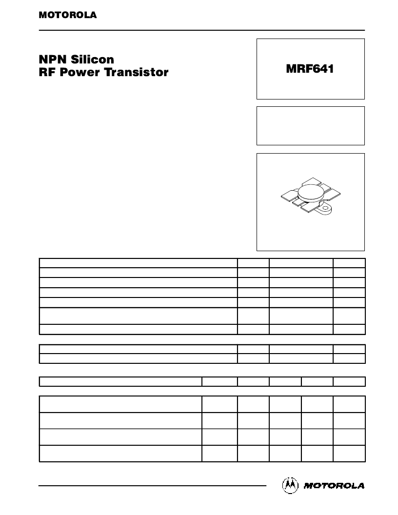
MRF641
MOTOROLA RF DEVICE DATA
Motorola, Inc. 1994
The RF Line
. . . designed for 12.5 Volt UHF large–signal amplifier applications in industrial
and commercial FM equipment operating to 512 MHz.
Specified 12.5 Volt, 470 MHz Characteristics —
Output Power = 15 Watts
Minimum Gain = 7.8 dB
Efficiency = 55%
Characterized with Series Equivalent Large–Signal Impedance Parameters
Built–In Matching Network for Broadband Operation
Tested for Load Mismatch Stress at all Phase Angles with 20:1 VSWR @
16–Volt High Line and Overdrive
Circuit board photomaster available upon request by contacting RF Tactical
Marketing in Phoenix, AZ.
MAXIMUM RATINGS
Rating
Symbol
Value
Unit
Collector–Emitter Voltage
VCEO
VCBO
VEBO
IC
PD
16
Vdc
Collector–Base Voltage
36
Vdc
Emitter–Base Voltage
4.0
Vdc
Collector Current — Continuous
3.0
Adc
Total Device Dissipation @ TC = 25
°
C
Derate above 25
°
C
43.7
0.25
Watts
W/
°
C
Storage Temperature Range
Tstg
–65 to +150
°
C
THERMAL CHARACTERISTICS
Characteristic
Symbol
Max
Unit
Thermal Resistance, Junction to Case
R
θ
JC
4.0
°
C/W
ELECTRICAL CHARACTERISTICS
(TC = 25
°
C unless otherwise noted.)
Characteristic
Symbol
Min
Typ
Max
Unit
OFF CHARACTERISTICS
Collector–Emitter Breakdown Voltage
(IC = 20 mAdc, IB = 0)
Collector–Emitter Breakdown Voltage
(IC = 20 mAdc, VBE = 0)
Emitter–Base Breakdown Voltage
(IE = 5.0 mAdc, IC = 0)
Collector Cutoff Current
(VCE = 15 Vdc, VBE = 0, TC = 25
°
C)
V(BR)CEO
16
—
—
Vdc
V(BR)CES
36
—
—
Vdc
V(BR)EBO
4.0
—
—
Vdc
ICES
—
—
5.0
mAdc
(continued)
Order this document
by MRF641/D
SEMICONDUCTOR TECHNICAL DATA
15 W, 470 MHz
CONTROLLED Q
RF POWER
TRANSISTOR
NPN SILICON
CASE 316–01, STYLE 1
REV 6
相關PDF資料 |
PDF描述 |
|---|---|
| MRF644 | RF POWER TRANSISTOR NPN SILICON |
| MRF650 | RF POWER TRANSISTOR NPN SILICON |
| MRF6522-70R3 | RF MOSFETS(RF MOS場效應管) |
| MRF652 | RF POWER TRANSISTORS NPN SILICON |
| MRF652S | RF POWER TRANSISTORS NPN SILICON |
相關代理商/技術參數(shù) |
參數(shù)描述 |
|---|---|
| MRF6414 | 制造商:MOTOROLA 制造商全稱:Motorola, Inc 功能描述:RF POWER TRANSISTOR NPN SILICON |
| MRF6414PHT | 制造商:MOTOROLA 制造商全稱:Motorola, Inc 功能描述:NPN Silicon RF Power Transistor |
| MRF644 | 制造商:MOTOROLA 功能描述:5961010973421 |
| MRF646 | 制造商:ASI 制造商全稱:ASI 功能描述:NPN SILICON RF POWER TRANSISTOR |
| MRF648 | 制造商:ASI 制造商全稱:ASI 功能描述:NPN SILICON RF POWER TRANSISTOR |
發(fā)布緊急采購,3分鐘左右您將得到回復。