- 您現(xiàn)在的位置:買賣IC網(wǎng) > PDF目錄359155 > MCZ33970EG (飛思卡爾半導體(中國)有限公司) Dual Gauge Driver Integrated Circuit with Improved Damping Algorithms PDF資料下載
參數(shù)資料
| 型號: | MCZ33970EG |
| 廠商: | 飛思卡爾半導體(中國)有限公司 |
| 英文描述: | Dual Gauge Driver Integrated Circuit with Improved Damping Algorithms |
| 中文描述: | 雙計驅(qū)動集成電路與改進的阻尼算法 |
| 文件頁數(shù): | 27/36頁 |
| 文件大?。?/td> | 430K |
| 代理商: | MCZ33970EG |
第1頁第2頁第3頁第4頁第5頁第6頁第7頁第8頁第9頁第10頁第11頁第12頁第13頁第14頁第15頁第16頁第17頁第18頁第19頁第20頁第21頁第22頁第23頁第24頁第25頁第26頁當前第27頁第28頁第29頁第30頁第31頁第32頁第33頁第34頁第35頁第36頁
Analog Integrated Circuit Device Data
Freescale Semiconductor
27
33970
FUNCTIONAL DEVICE OPERATION
LOGIC COMMANDS AND REGISTERS
percent due to process variation. Using the existing SPI
inputs and the precision timing reference already available to
the microcontroller, the 33970 allows clock calibration to
within ±10 percent.
Calibrating the internal 1.0 MHz clock is initiated by writing
a logic [1] to PECCR bit PE3 (see
Figure 10
, page
27
). The
8.0
μ
s calibration pulse that is then provided by the controller
will ideally result in an internal 33970 clock speed of 1.0 MHz.
The pulse is sent on the
CS
pin immediately after the SPI
word is sent. No other SPI lines should be toggled. At the
moment the CS pin transitions from logic [1] to logic [0], an
internal 7-bit counter counts the number of cycles of an
internal 8.0 MHz clock. The counter stops when the
CS
pin
transitions from logic [0] to logic [1]. The value in the counter
represents the number of cycles of the 8.0 MHz clock
occurring in the 8.0
μ
s window; it should range from 32 to
119. An offset is added to this number to help center or skew
the calibrated result to generate a desired maximum or
nominal frequency. The modified counter value is truncated
by 4 bits to generate the calibration divisor, which should
range from 4 to 15. The 8.0 MHz clock is divided by the
calibration divisor, resulting in a calibrated 1.0 MHz clock. If
the calibration divisor lies outside the range of 4 to 15, the
33970 flags the CAL bit of the status bits, indicating the
calibration procedure was not successful. A clock calibration
is allowed only if the gauges are disabled or the pointers are
not moving, as indicated by status bits MOV1 and MOV0.
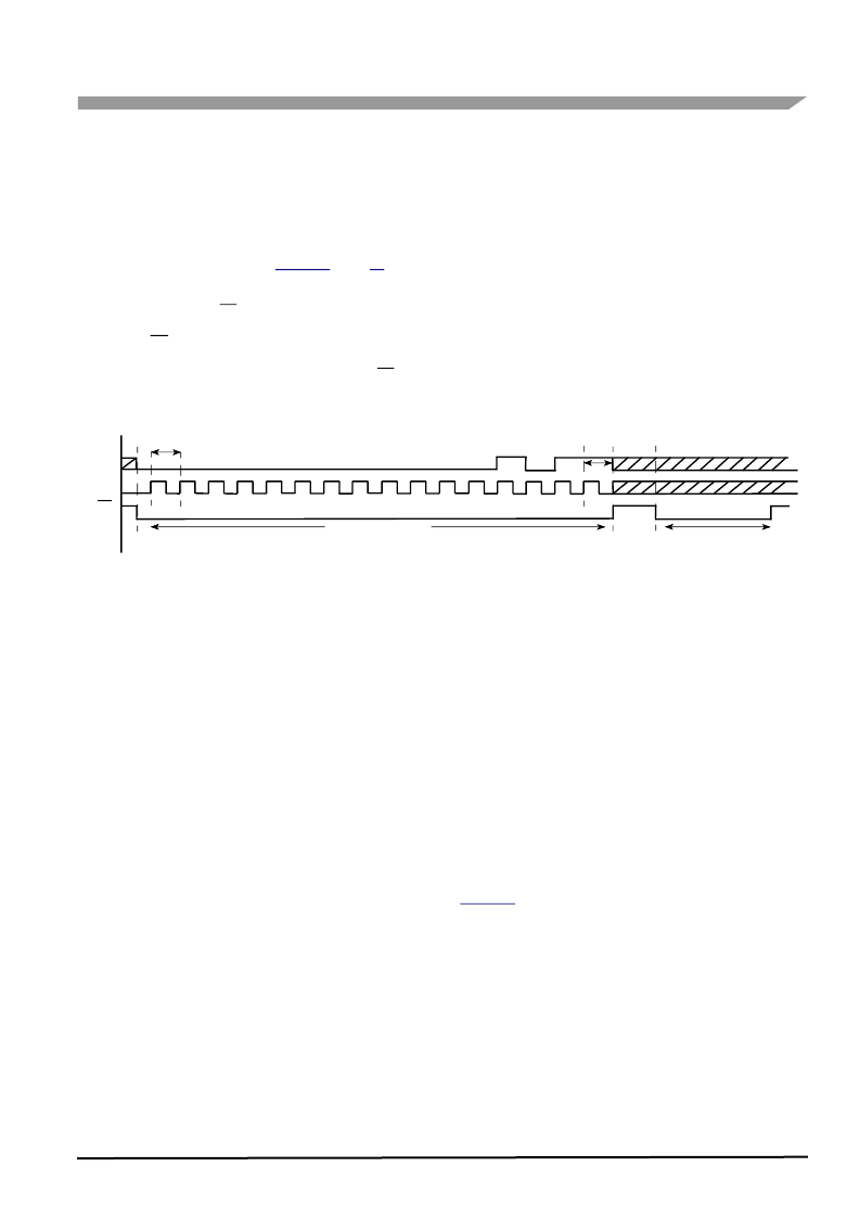
Figure 10. Gauge Enable and Clock Calibration Example
Some applications may require a guaranteed maximum
pointer velocity and acceleration. Guaranteeing these
maximums requires nominal internal clock frequency falls
below 1.0 MHz. The frequency range of the calibrated clock
will always be below 1.0 MHz if PECCR bit PE4 is logic [0]
prior to initiating a calibration command, followed by an
8.0
μ
s reference pulse. The frequency will be centered at
1.0 MHz if bit D4 is logic [1].
The
33970 can be fooled into calibrating faster or slower
than the optimal frequency by sending a calibration pulse
longer or shorter than the intended 8.0
μ
s. As long as the
count remains between 4 and 15, there will be no clock
calibration flag. For applications requiring a slower calibrated
clock — e.g., a motor designed with a gear ratio of 120:1
(8 microsteps/deg) — the user will have to provide a longer
calibration pulse. The device allows a SPI-selectable slowing
of the internal oscillator, using the PECCR command, so that
the calibration divisor safely falls within the 4-to-15 range
when calibrating with a longer time reference. For example,
for the 120:1 motor, the pulse would be 12
μ
s instead of
8.0
μ
s. The result of this slower calibration results in the
longer step times necessary to generate pointer movements
meeting acceleration and velocity requirements. The
resolution of the pointer positioning decreases from
0.083 deg/microstep (180:1) to 0.125 deg/microstep (120:1).
The pointer sweep range increases from approximately
340 degrees to over 500 degrees.
Note
Be aware that a fast calibration could result in
violations of the motor acceleration and velocity maximums,
resulting in missed steps.
POINTER DECELERATION
Constant acceleration and deceleration of the pointer
produces relatively choppy movements when compared to
those of an air core gauge. Air core behavior can be
simulated with appropriate ramp modification during
deceleration. This shaping can be accomplished by adding
repetitive steps at several of the last step values as the
pointer decelerates. The default movement in the 33970 uses
this ramp modification feature. An example is shown in
Figure 11
. If the maximum acceleration and deceleration of
the pointer is desired, the repetitive steps can be disabled by
writing logic [1] to the PECCR bit PE5.
D15
SI
SCLK
CS
PECCR Command
D0
8.0
μ
s Calibration Pulse
相關(guān)PDF資料 |
PDF描述 |
|---|---|
| MCZ33976EG | Dual Gauge Driver with Configurable esponse Time |
| MCZ33977EG | Single Gauge Driver |
| MCZ33989EG | System Basis Chip with High-Speed CAN Transceiver |
| MCZ33990EF | Enhanced Class B Serial Transceiver |
| MCZ33991EG | Gauge Driver Integrated Circuit |
相關(guān)代理商/技術(shù)參數(shù) |
參數(shù)描述 |
|---|---|
| MCZ33970EG | 制造商:Freescale Semiconductor 功能描述:IC STEPPER MOTOR GAUGE DRIVER SPI |
| MCZ33970EGR2 | 功能描述:馬達/運動/點火控制器和驅(qū)動器 DUAL GAGE DRVR IMP DAMP RoHS:否 制造商:STMicroelectronics 產(chǎn)品:Stepper Motor Controllers / Drivers 類型:2 Phase Stepper Motor Driver 工作電源電壓:8 V to 45 V 電源電流:0.5 mA 工作溫度:- 25 C to + 125 C 安裝風格:SMD/SMT 封裝 / 箱體:HTSSOP-28 封裝:Tube |
| MCZ33972AEK | 功能描述:接口 - 專用 MULT SW DET SUP-WKUP RoHS:否 制造商:Texas Instruments 產(chǎn)品類型:1080p60 Image Sensor Receiver 工作電源電壓:1.8 V 電源電流:89 mA 最大功率耗散: 最大工作溫度:+ 85 C 安裝風格:SMD/SMT 封裝 / 箱體:BGA-59 |
| MCZ33972AEK/R2 | 制造商:FREESCALE 制造商全稱:Freescale Semiconductor, Inc 功能描述:Multiple Switch Detection Interface with Suppressed Wake-up |
| MCZ33972AEKR2 | 功能描述:接口 - 專用 MULT SW DET SUP-WKUP RoHS:否 制造商:Texas Instruments 產(chǎn)品類型:1080p60 Image Sensor Receiver 工作電源電壓:1.8 V 電源電流:89 mA 最大功率耗散: 最大工作溫度:+ 85 C 安裝風格:SMD/SMT 封裝 / 箱體:BGA-59 |
發(fā)布緊急采購,3分鐘左右您將得到回復。