- 您現(xiàn)在的位置:買賣IC網(wǎng) > PDF目錄385497 > LPC2377FBD144 (NXP SEMICONDUCTORS) Single-chip 16-bit-32-bit microcontrollers; 512 kB flash with ISP-IAP, Ethernet, USB 2.0, CAN, and 10-bit ADC-DAC PDF資料下載
參數(shù)資料
| 型號: | LPC2377FBD144 |
| 廠商: | NXP SEMICONDUCTORS |
| 元件分類: | 微控制器/微處理器 |
| 英文描述: | Single-chip 16-bit-32-bit microcontrollers; 512 kB flash with ISP-IAP, Ethernet, USB 2.0, CAN, and 10-bit ADC-DAC |
| 中文描述: | 32-BIT, FLASH, 25 MHz, RISC MICROCONTROLLER, PQFP144 |
| 封裝: | 20 X 20 MM, 1.40 MM HEIGHT, PLASTIC, MS-026, SOT486-1, LQFP-144 |
| 文件頁數(shù): | 59/68頁 |
| 文件大?。?/td> | 1443K |
| 代理商: | LPC2377FBD144 |
第1頁第2頁第3頁第4頁第5頁第6頁第7頁第8頁第9頁第10頁第11頁第12頁第13頁第14頁第15頁第16頁第17頁第18頁第19頁第20頁第21頁第22頁第23頁第24頁第25頁第26頁第27頁第28頁第29頁第30頁第31頁第32頁第33頁第34頁第35頁第36頁第37頁第38頁第39頁第40頁第41頁第42頁第43頁第44頁第45頁第46頁第47頁第48頁第49頁第50頁第51頁第52頁第53頁第54頁第55頁第56頁第57頁第58頁當(dāng)前第59頁第60頁第61頁第62頁第63頁第64頁第65頁第66頁第67頁第68頁
LPC2377_78
All information provided in this document is subject to legal disclaimers.
NXP B.V. 2010. All rights reserved.
Product data sheet
Rev. 5 — 17 June 2010
59 of 68
NXP Semiconductors
LPC2377/78
Single-chip 16-bit/32-bit microcontrollers
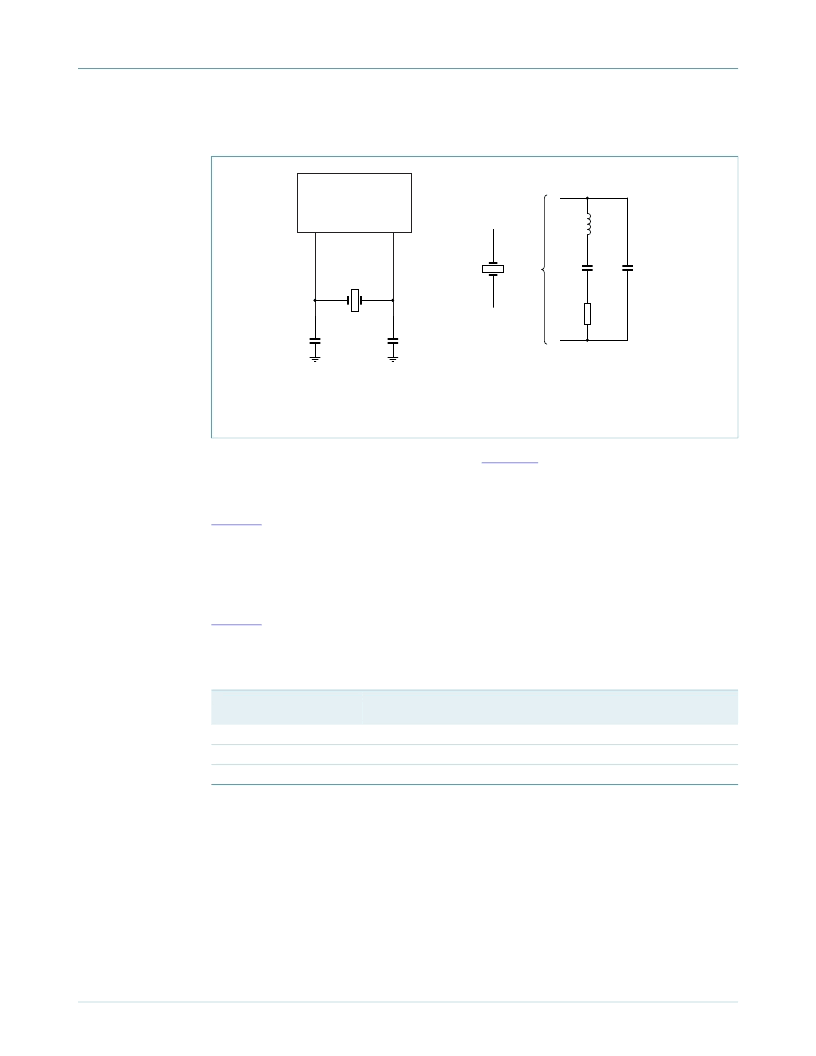
14.3 RTC 32 kHz oscillator component selection
The RTC external oscillator circuit is shown in
Figure 23
. Since the feedback resistance is
integrated on chip, only a crystal, the capacitances C
X1
and C
X2
need to be connected
externally to the microcontroller.
Table 17
gives the crystal parameters that should be used. C
L
is the typical load
capacitance of the crystal and is usually specified by the crystal manufacturer. The actual
C
L
influences oscillation frequency. When using a crystal that is manufactured for a
different load capacitance, the circuit will oscillate at a slightly different frequency
(depending on the quality of the crystal) compared to the specified one. Therefore for an
accurate time reference it is advised to use the load capacitors as specified in Table
Table 17
that belong to a specific C
L
. The value of external capacitances C
X1
and C
X2
specified in this table are calculated from the internal parasitic capacitances and the C
L
.
Parasitics from PCB and package are not taken into account.
Table 17.
Crystal load capacitance
C
L
11 pF
13 pF
15 pF
14.4 XTAL and RTCX Printed Circuit Board (PCB) layout guidelines
The crystal should be connected on the PCB as close as possible to the oscillator input
and output pins of the chip. Take care that the load capacitors C
x1
, C
x2
, and C
x3
in case of
third overtone crystal usage have a common ground plane. The external components
must also be connected to the ground plain. Loops must be made as small as possible in
order to keep the noise coupled in via the PCB as small as possible. Also parasitics
should stay as small as possible. Values of C
x1
and C
x2
should be chosen smaller
accordingly to the increase in parasitics of the PCB layout.
Fig 23. RTC oscillator modes and models: oscillation mode of operation and external
crystal model used for C
X1
/C
X2
evaluation
Recommended values for the RTC external 32 kHz oscillator C
X1
/C
X2
components
Maximum crystal series
resistance R
S
< 100 k
Ω
< 100 k
Ω
< 100 k
Ω
External load capacitors C
X1
/C
X2
18 pF, 18 pF
22 pF, 22 pF
27 pF, 27 pF
002aaf495
LPC2xxx
RTCX1
RTCX2
CX2
CX1
32 kHz XTAL
=
CL
CP
RS
L
發(fā)布緊急采購,3分鐘左右您將得到回復(fù)。