- 您現(xiàn)在的位置:買賣IC網(wǎng) > PDF目錄385474 > LM1229 (National Semiconductor Corporation) I2C Compatible CMOS TV RGB and Deflection Processor PDF資料下載
參數(shù)資料
| 型號: | LM1229 |
| 廠商: | National Semiconductor Corporation |
| 英文描述: | I2C Compatible CMOS TV RGB and Deflection Processor |
| 中文描述: | I2C兼容的CMOS電視RGB和偏轉(zhuǎn)處理器 |
| 文件頁數(shù): | 22/27頁 |
| 文件大小: | 969K |
| 代理商: | LM1229 |
第1頁第2頁第3頁第4頁第5頁第6頁第7頁第8頁第9頁第10頁第11頁第12頁第13頁第14頁第15頁第16頁第17頁第18頁第19頁第20頁第21頁當(dāng)前第22頁第23頁第24頁第25頁第26頁第27頁
Application Register Detail
(Continued)
(0V–2.1V).
Bit 4: When set to 0, vertical blanking of the RGB outputs is disabled. When set to 1, vertical blanking is enabled.
Bit 3: When set to 0, the LM1229 clamps the input video when the input clamp pulse is high. When set to 1 the LM1229 expects
a negative going pulse.
Bit 2: When set to 0, horizontal blanking at the RGB outputs is disabled. When set to 1, horizontal blanking is enabled.
Bit 1: When set to 0, the LM1229 is in normal operation. When set to 1, it is put into the power save mode for reduced power
consumption.
Bit 0: When set to 0, normal video appears at the RGB outputs. When set to 1, the RGB outputs are set to the blanking level as
given in the specification section.
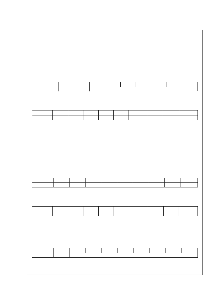
OSD TRANSPARENCY
Register
OSD TRANS
Addr
0x0A
Bit 7
X
Bit 6
Bit 5
Bit 4
Bit 3
Bit 2
Bit 1
Bit 0
OSD TRANS[6:0]
Bits 6–0: These bits determine the amount of video in the OSD background at the times when the OSD Enable input is active
and when there is no OSD foreground. When set to 0x00, the video background is at minimum contrast and when set
to 0x7F, the video background is at maximum contrast.
OSD Control
Register
OSD
Addr
0x0B
Bit 7
OOR
Bit 6
X
Bit 5
AUX
Bit 4
DA
Bit 3
TRANS
Bit 2
X
Bit 1
OSD_Cont[1:0]
Bit 0
Bit 7:
This is the OSD override bit. This will be read as a 0 for normal operation. When set to a 1, the video outputs are
disconnected and OSD only is displayed. This is useful for the OSD display of special conditions such as “No Signal”,
or other information to the user.
This bit controls whether the analog OSD gain is set to maximum. When this bit is a 0 and bit 4 is a 1, the analog OSD
output levels are determined by the input level and OSD_Cont[1:0]. When this bit is a 1 and DA is a 1, the output levels
are determined by the input level only, with a gain of 4.14. When DA is a 0 for digital OSD inputs, this bit has no effect.
See
Table 3
.
When set to a 0, the LM1229 is configured for digital OSD inputs. When set to a 1, the OSD inputs are configured for
0V–0.7V analog.
When set to a 0, the OSD background is determined by the OSD Enable input, such that when the enable is active the
video is set to black. When this bit is set to a 1 the OSD background is video attenuated by the OSD Transparency
register, 0x0A, but only while the OSD Enable input is a 1. See
Table 2
.
Bits 1–0: These bits determine the contrast level of the OSD. Refer to
Table 3
for amplitudes.
RESET
Bit 5:
Bit 4:
Bit 3:
Register
RESET
Addr
0x0C
Bit 7
X
Bit 6
X
Bit 5
X
Bit 4
X
Bit 3
X
Bit 2
X
Bit 1
X
Bit 0
SRST
Bit 0: Setting this bit to a 1 causes a software reset. All registers (except this one) are loaded with their default values. All
operations currently in progress are aborted (except for I
2
C transactions). This bit automatically clears itself when the reset
has been completed.
STATUS
Register
STATUS
Addr
0x40
Bit 7
X
Bit 6
X
Bit 5
X
Bit 4
X
Bit 3
VPROT
Bit 2
XRay
Bit 1
FBP
Bit 0
HLOCK
Bit 3: This is the Vertical Protection status. This bit is a 0 for normal operation, and is a 1 if Vertical Protection is triggered and
the R, G, B, video outputs are blanked. This will reset to 0 when a good vertical drive signal is present.
Bit 2: This bit is 0 if X-Ray is not triggered, 1 if X-Ray triggered. It will reset to 0 when V
CC
≤
4V.
Bit 1: Flyback pulse, 0 if good flyback pulse present, 1 if bad flyback pulse or no flyback pulse.
Bit 0: This is the horizontal deflection lock bit. It is 1 if HSYNC is present and the PLL is locked to it. It is a 0 if no HSYNC is
present or if the PLL is not locked to HSYNC.
HORIZONTAL POSITION
Register
HPOS
Addr
0x41
Bit 7
Bit 6
Bit 5
Bit 4
Bit 3
Bit 2
Bit 1
Bit 0
HPOS[7:0]
Bits 7–0: Sets the horizontal position of the picture on the CRT. When set to minimum the picture is to the left, and when set to
maximum the picture is to the right.
L
www.national.com
22
相關(guān)PDF資料 |
PDF描述 |
|---|---|
| LM1229VEC | I2C Compatible CMOS TV RGB and Deflection Processor |
| LM1229YA | I2C Compatible CMOS TV RGB and Deflection Processor |
| LM1247 | 150 MHz I2C Compatible RGB Preamplifier with Internal 512 Character OSD ROM, 512 Character RAM and 4 DACs |
| LM1270 | Hi-Brite 200 MHz I2C Compatible RGB Image Enhancer with Video Auto Sizing |
| LM1270N | Hi-Brite 200 MHz I2C Compatible RGB Image Enhancer with Video Auto Sizing |
相關(guān)代理商/技術(shù)參數(shù) |
參數(shù)描述 |
|---|---|
| LM1229VEC | 制造商:NSC 制造商全稱:National Semiconductor 功能描述:I2C Compatible CMOS TV RGB and Deflection Processor |
| LM1229YA | 制造商:NSC 制造商全稱:National Semiconductor 功能描述:I2C Compatible CMOS TV RGB and Deflection Processor |
| LM122H | 制造商:QP Semiconductor 功能描述:Precision Timer 10-Pin TO-100 |
| LM122H/883 | 制造商:QP Semiconductor 功能描述:Precision Timer |
| LM122H-MIL | 制造商:未知廠家 制造商全稱:未知廠家 功能描述:Analog Timer Circuit |
發(fā)布緊急采購,3分鐘左右您將得到回復(fù)。