- 您現(xiàn)在的位置:買賣IC網(wǎng) > PDF目錄358765 > LC78625 (Sanyo Electric Co.,Ltd.) SigmaDSP 28-/56-Bit Audio Processor with Two ADCs and Four DACs PDF資料下載
參數(shù)資料
| 型號: | LC78625 |
| 廠商: | Sanyo Electric Co.,Ltd. |
| 元件分類: | 數(shù)字信號處理 |
| 英文描述: | SigmaDSP 28-/56-Bit Audio Processor with Two ADCs and Four DACs |
| 中文描述: | SigmaDSP的28-/56-Bit音頻處理器雙ADC和4個DAC |
| 文件頁數(shù): | 22/35頁 |
| 文件大?。?/td> | 440K |
| 代理商: | LC78625 |
第1頁第2頁第3頁第4頁第5頁第6頁第7頁第8頁第9頁第10頁第11頁第12頁第13頁第14頁第15頁第16頁第17頁第18頁第19頁第20頁第21頁當(dāng)前第22頁第23頁第24頁第25頁第26頁第27頁第28頁第29頁第30頁第31頁第32頁第33頁第34頁第35頁
No. 5502-22/35
LC78625E
12. Level meter (LVM) data and peak meter (PKM) data readout
Level meter (LVM)
— The LVM set command ($2C) sets the LC78625E to LVM mode.
— LVM data is a 16-bit word in which the MSB indicates the L/R polarity and the low-order 15 bits are absolute
value data. A one in the MSB indicates left channel data and a zero indicates right channel data.
— LVM data is appended after the 80 bits of subcode Q data, and can be read out by applying 96 clock cycles to the
CQCK pin. Each time LVM data is read out the left/right channel state is inverted. Data is held independently for
both the left and right channels. In particular, the largest value that occurs between readouts for each channel is
held.
Peak meter (PKM)
— The PKM set command ($2B) sets the LC78625E to PKM mode.
— PKM data is a 16-bit word in which the MSB is always zero and the low-order 15 bits are absolute value data. This
functions detects the maximum value that occurs in the data, whichever channel that value occurs in.
— PKM data is read out in the same manner as LVM data. However, data is not updated as a result of the readout
operation.
— The absolute time for PKM mode subcode Q data is computed by holding the absolute time (ATIME) detected after
the maximum value occurred and sending that value. (Normal operation uses relative time.)
— It is possible to set the LC78625E to ignore values larger than the already recorded value by issuing the PKM mask
set command, even in PKM mode. This function is cleared by issuing a PKM mask reset command. (This is used in
PK search in a memory track.)
13. Mute control circuit
An attenuation of 12 dB (MUTE –12 dB) or full muting (MUTE
∞
dB) can be applied by issuing the appropriate
command from the table. Since zero cross muting is used, there is minimal noise associated with this function. Zero
cross is defined for this function as the top seven bits being all ones or all zeros.
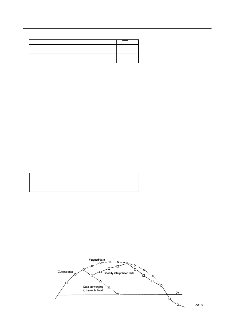
14. Interpolation circuit
Outputting incorrect audio data that could not be corrected by the error detection and correction circuit would result
in loud noises being output. To minimize this noise, the LC78625E replaces the incorrect data with linearly
interpolated data based on the correct data on either side of the incorrect data. More precisely, the LC78625E uses
this technique if C2 flags occurred up to three times in a row. If C2 flags occurred four or more times in a row, the
LC78625E converges the output level to the muting level. However, when correct data is finally output following
four or more C2 flag occurrences, the LC78625E replaces the 3 data items between the data output four items
previously and the correct data with linearly interpolated data.
Code
COMMAND
RES = L
$2B
PKM Set (LVM Reset)
$2C
LVM Set (PKM Reset)
G
$2D
PKM mask set
$2E
PKM mask reset
G
G
Code
COMMAND
RES = L
$01
MUTE
0 dB
$02
MUTE
–12 dB
–
∞
dB
$03
MUTE
G
G
相關(guān)PDF資料 |
PDF描述 |
|---|---|
| LC78626KE | Compact Disc Player DSP(用于CD播放器的8位DSP) |
| LC78626 | 16-bit fixed point DSP with Flash |
| LC78626E | 16-bit fixed point DSP with Flash |
| LC78628 | 16-bit fixed point DSP with Flash |
| LC78628E | 16-bit fixed point DSP with Flash |
相關(guān)代理商/技術(shù)參數(shù) |
參數(shù)描述 |
|---|---|
| LC78625E | 制造商:SANYO 制造商全稱:Sanyo Semicon Device 功能描述:Compact Disc Player DSP |
| LC78626 | 制造商:SANYO 制造商全稱:Sanyo Semicon Device 功能描述:DSP for Compact Disk Players |
| LC78626E | 制造商:SANYO 制造商全稱:Sanyo Semicon Device 功能描述:DSP for Compact Disk Players |
| LC78626KE | 制造商:未知廠家 制造商全稱:未知廠家 功能描述:CD-Player Processor/Controller |
| LC78628 | 制造商:SANYO 制造商全稱:Sanyo Semicon Device 功能描述:Compact Disc Player DSP with Built-in HDCD Decoder |
發(fā)布緊急采購,3分鐘左右您將得到回復(fù)。