- 您現(xiàn)在的位置:買(mǎi)賣(mài)IC網(wǎng) > PDF目錄358737 > LA7615 (Sanyo Electric Co.,Ltd.) Single-Chip NTSC Color TV IC PDF資料下載
參數(shù)資料
| 型號(hào): | LA7615 |
| 廠商: | Sanyo Electric Co.,Ltd. |
| 英文描述: | Single-Chip NTSC Color TV IC |
| 中文描述: | 單片集成電路NTSC制式彩電 |
| 文件頁(yè)數(shù): | 3/39頁(yè) |
| 文件大?。?/td> | 206K |
| 代理商: | LA7615 |
第1頁(yè)第2頁(yè)當(dāng)前第3頁(yè)第4頁(yè)第5頁(yè)第6頁(yè)第7頁(yè)第8頁(yè)第9頁(yè)第10頁(yè)第11頁(yè)第12頁(yè)第13頁(yè)第14頁(yè)第15頁(yè)第16頁(yè)第17頁(yè)第18頁(yè)第19頁(yè)第20頁(yè)第21頁(yè)第22頁(yè)第23頁(yè)第24頁(yè)第25頁(yè)第26頁(yè)第27頁(yè)第28頁(yè)第29頁(yè)第30頁(yè)第31頁(yè)第32頁(yè)第33頁(yè)第34頁(yè)第35頁(yè)第36頁(yè)第37頁(yè)第38頁(yè)第39頁(yè)

Furthermore, this IC also supports high image quality systems and responds to needs from a diverse range of end
products.
Two independent inputs for the luminance and chrominance signals and switching between the Y1/C1 and Y2/C2 inputs
Video muting on/off switch
Built-in filters (The filter f0 adjustment function can be used to select the filter characteristics.)
Chrominance system: Bandpass filter (symmetric and asymmetric types)
Luminance system: Color trap and delay line
<Luminance System Circuit>
Built-in high image quality variable-type luminance system filter (color trap and delay line)
Luminance filter mode selection (f0 adjustment)
Four modes are provided: 3.58 MHz trap, 4.2 MHz trap, 5.0 MHz wide, and 10.0 MHz high band.
Peaking (sharpness) control
Aperture type control implemented using the delay line
The emphasis frequency is automatically selected according to the f0 mode using the delay line.
One of the four frequencies 2.2, 2.6, 3.0, or 4.9 MHz is emphasized according to which of the f0 modes (3.58 MHz
trap, 4.2 MHz trap, 5.0 MHz wide, or 10.0 MHz high band) is used.
Adaptive coring
For low-level signals, the above peaking is suppressed to reduce the image contamination due to that peaking.
The coring level is automatically adjusted according to the amplitude of the input signal.
Black stretch circuit: Can be turned on or off under control of the serial bus interface.
SYO (Selected luminance (Y) output)
One of the Y1/Y2 inputs is selected, and that input signal is output as the sync separator circuit signal directly.
However, the DC level of that signal is clamped at 1/2 VCC.
Also, this signal can be used for closed captions or as a velocity modulation.
Support for analog/digital OSD
Amplitude level limiting is applied to digital input signals internally to the IC.
Contrast and brightness controls
ABL (automatic beam limiter)
Three-pin system (IB IN, BRT ABL FILT, and CONTRAST ABL FILT pins), mode switching under control of serial
bus data.
R, G, and B output drive and bias adjustments
Sub-bias (brightness) control
The DC level of each of the R, G, and B signals can be adjusted over a 4-step (2-bit) range.
<Chrominance Circuit>
Built-in chrominance bandpass filter
Chrominance system filter mode selection: bandpass filter peaking/symmetric type selection and chrominance
bandpass filter bypass on/off setting
Auto Flesh: Flesh tone correction (on/off)
Overload (on/off)
Limits the saturation of the color when the ratio of the burst and color signals is large, i.e. when the color is highly
saturated.
Color phase and saturation controls
Demodulation angle: 104°
No. 5841-3/39
LA7615
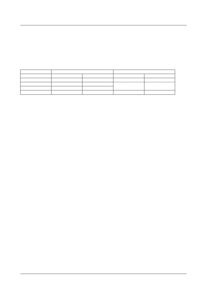
<f0 Mode Selection>
*
: Reference values
Mode f0 =
Y signal
Chroma signal
Trap f0
*
Total delay
BPF
*
Total 500 ns delay
0
3.58 MHz
500 ns
Asymmetric (peaking type)
515 ns
1
4.2 MHz
510 ns
Symmetric
535 ns
2
5.0 MHz
520 ns
3
10.0 MHz
265 ns
Bypass
265 ns
相關(guān)PDF資料 |
PDF描述 |
|---|---|
| LA7620 | Color TV Video, Chroma, Deflection Circuit |
| LA7625 | Video, Chroma and Deflection Circuit for Color Television Sets |
| LA7629 | Color TV/Video,Chroma,Deflection Circuit |
| LA7640N | Chroma Circuit for SECAM-system Color Television Sets |
| LA7642N | SECAM Format Color TV Chrominance Circuit |
相關(guān)代理商/技術(shù)參數(shù) |
參數(shù)描述 |
|---|---|
| LA7620 | 制造商:SANYO 制造商全稱:Sanyo Semicon Device 功能描述:Color TV Video, Chroma, Deflection Circuit |
| LA7621 | 制造商:Panasonic Industrial Company 功能描述:IC |
| LA7625 | 制造商:SANYO 制造商全稱:Sanyo Semicon Device 功能描述:Video, Chroma and Deflection Circuit for Color Television Sets |
| LA7626 | 制造商:SANYO 制造商全稱:Sanyo Semicon Device 功能描述:Video, Chroma and Deflection Circuit for Color Television Sets |
| LA7629 | 制造商:SANYO 制造商全稱:Sanyo Semicon Device 功能描述:Color TV/Video,Chroma,Deflection Circuit |
發(fā)布緊急采購(gòu),3分鐘左右您將得到回復(fù)。