- 您現在的位置:買賣IC網 > PDF目錄358737 > LA7615 (Sanyo Electric Co.,Ltd.) Single-Chip NTSC Color TV IC PDF資料下載
參數資料
| 型號: | LA7615 |
| 廠商: | Sanyo Electric Co.,Ltd. |
| 英文描述: | Single-Chip NTSC Color TV IC |
| 中文描述: | 單片集成電路NTSC制式彩電 |
| 文件頁數: | 21/39頁 |
| 文件大?。?/td> | 206K |
| 代理商: | LA7615 |
第1頁第2頁第3頁第4頁第5頁第6頁第7頁第8頁第9頁第10頁第11頁第12頁第13頁第14頁第15頁第16頁第17頁第18頁第19頁第20頁當前第21頁第22頁第23頁第24頁第25頁第26頁第27頁第28頁第29頁第30頁第31頁第32頁第33頁第34頁第35頁第36頁第37頁第38頁第39頁
No. 5841-21/39
LA7615
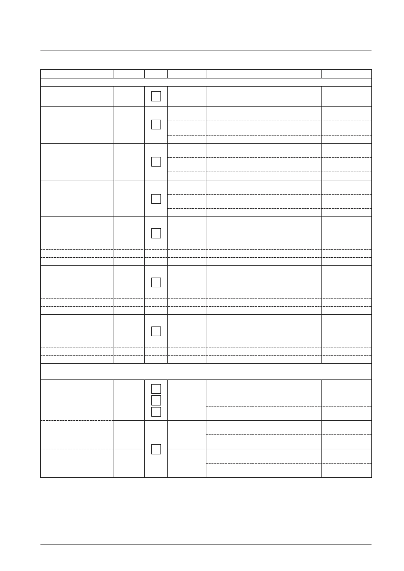
Continued from preceding page.
Parameter
Symbol
Test point
Input signal
Test procedure
Bus bits/input signal
[OSD Block]
OSD fast switching threshold
RGB red output level
RGB green output level
RGB blue output level
Analog OSD red output level
Gain matching
Linearity
Analog OSD green output level
Gain matching
Linearity
Analog OSD blue output level
Gain matching
Linearity
[RGB Output Block]
(Cutoff and Drive Blocks)
Brightness control
(normal)
(maximum)
(minimum)
FS
TH
R
OSDH
G
OSDH
B
OSDH
R
RGB
LR
RGB
G
RGB
LG
RGB
B
RGB
LB
RGB
BRT32
BRT63
BRT0
L-0
O-2
L-50
L-0
O-2
L-50
L-0
O-2
L-50
L-0
O-2
L-0
O-1
L-0
O-1
L-0
O-1
L-0
Gradually increase the pin 39 voltage starting at 1.5
V, and determine the pin 39 voltage at the point
where the output signal switches to the OSD signal.
Measure the 50 IRE amplitude in the output signal.
(CNT
CR
Vp-p).
Measure the OSD output amplitude (OSD
HR
Vp-p).
Calculate R
OSDH
= 50
×
(OSD
HR
/CNT
CR
).
Measure the 50 IRE amplitude in the output signal.
(CNT
CG
Vp-p).
Measure the OSD output amplitude (OSD
HG
Vpp).
Calculate G
OSDH
= 50
×
(OSD
HG
/CNT
CG
).
Measure the 50 IRE amplitude in the output signal.
(CNTCB Vp-p).
Measure the OSD output amplitude (OSD
HB
Vp-p).
Calculate B
OSDH
= 50
×
(OSD
HB
/CNT
CB
).
Measure the amplitudes at point A (the 0.35 V
component of the input signal O-1) and point B (the
0.7 V component of the input signal O-1) in the
output signal and record these as RGB
LR
and
RGB
HR
(Vp-p) respectively.
Calculate R
RGB
= RGB
LR
/CNT
CR
.
Calculate LR
RGB
= 100
×
(RGB
LR
/RGB
HR
).
Measure the amplitudes at point A (the 0.35 V
component of the input signal O-1) and point B (the
0.7 V component of the input signal O-1) in the
output signal and record these as RGB
LG
and
RGB
HG
(Vp-p) respectively.
Calculate G
RGB
= RGB
LG
/CNT
CG
.
Calculate LG
RGB
= 100
×
(RGB
LG
/RGB
HG
).
Measure the amplitudes at point A (the 0.35 V
component of the input signal O-1) and point B (the
0.7 V component of the input signal O-1) in the
output signal and record these as RGB
LB
and
RGB
HB
(Vp-p) respectively.
Calculate B
RGB
= RGB
LB
/CNT
CB
.
Calculate LB
RGB
= 100
×
(RGB
LB
/RGB
HB
).
Measure the output signal 0 IRE DC levels of the R
output (pin 36), G output (pin 37), and B output (pin
38) and record these as BRTPC
R
, BRTPC
G
, and
BRTPC
B
(V), respectively.
Calculate
BRT63 = (BRTPC
R
+ BRTPC
G
+ BRTPC
B
)/3.
Measure the output signal 0 IRE DC level of the B
output (pin 38) (BRTPH
B
).
Calculate
BRT63 = 50
×
(BRTPH
B
– BRTPC
B
) / CNTH
B
.
Measure the output signal 0 IRE DC level of the B
output (pin 38) (BRTPL
B
).
Calculate
BRT0 = 50
×
(BRTPL
B
– BRTPC
B
) / CNTH
B
.
Pin 42:Apply signal
O-2.
Pin 39: Apply 3.5 V.
Pin 40: Apply signal O-2.
Pin 39: Apply 3.5 V.
Pin 41: Apply signal O-2.
Pin 39: Apply 3.5 V.
Pin 42: Apply signal O-2.
Pin 39: Apply 3.5 V.
Pin 40: Apply signal
O-1.
Pin 39: Apply 3.5 V.
Pin 34: Apply signal
O-1.
Pin 39: Apply 3.5 V.
Pin 41: Apply signal
O-1.
TR24: Contrast
111111
TR23: Brightness
111111
TR23: Brightness
000000
38
36
37
38
36
37
38
36
37
38
38
Continued on next page.
相關PDF資料 |
PDF描述 |
|---|---|
| LA7620 | Color TV Video, Chroma, Deflection Circuit |
| LA7625 | Video, Chroma and Deflection Circuit for Color Television Sets |
| LA7629 | Color TV/Video,Chroma,Deflection Circuit |
| LA7640N | Chroma Circuit for SECAM-system Color Television Sets |
| LA7642N | SECAM Format Color TV Chrominance Circuit |
相關代理商/技術參數 |
參數描述 |
|---|---|
| LA7620 | 制造商:SANYO 制造商全稱:Sanyo Semicon Device 功能描述:Color TV Video, Chroma, Deflection Circuit |
| LA7621 | 制造商:Panasonic Industrial Company 功能描述:IC |
| LA7625 | 制造商:SANYO 制造商全稱:Sanyo Semicon Device 功能描述:Video, Chroma and Deflection Circuit for Color Television Sets |
| LA7626 | 制造商:SANYO 制造商全稱:Sanyo Semicon Device 功能描述:Video, Chroma and Deflection Circuit for Color Television Sets |
| LA7629 | 制造商:SANYO 制造商全稱:Sanyo Semicon Device 功能描述:Color TV/Video,Chroma,Deflection Circuit |
發(fā)布緊急采購,3分鐘左右您將得到回復。