- 您現(xiàn)在的位置:買賣IC網(wǎng) > PDF目錄358737 > LA7615 (Sanyo Electric Co.,Ltd.) Single-Chip NTSC Color TV IC PDF資料下載
參數(shù)資料
| 型號: | LA7615 |
| 廠商: | Sanyo Electric Co.,Ltd. |
| 英文描述: | Single-Chip NTSC Color TV IC |
| 中文描述: | 單片集成電路NTSC制式彩電 |
| 文件頁數(shù): | 15/39頁 |
| 文件大小: | 206K |
| 代理商: | LA7615 |
第1頁第2頁第3頁第4頁第5頁第6頁第7頁第8頁第9頁第10頁第11頁第12頁第13頁第14頁當(dāng)前第15頁第16頁第17頁第18頁第19頁第20頁第21頁第22頁第23頁第24頁第25頁第26頁第27頁第28頁第29頁第30頁第31頁第32頁第33頁第34頁第35頁第36頁第37頁第38頁第39頁
No. 5841-15/39
LA7615
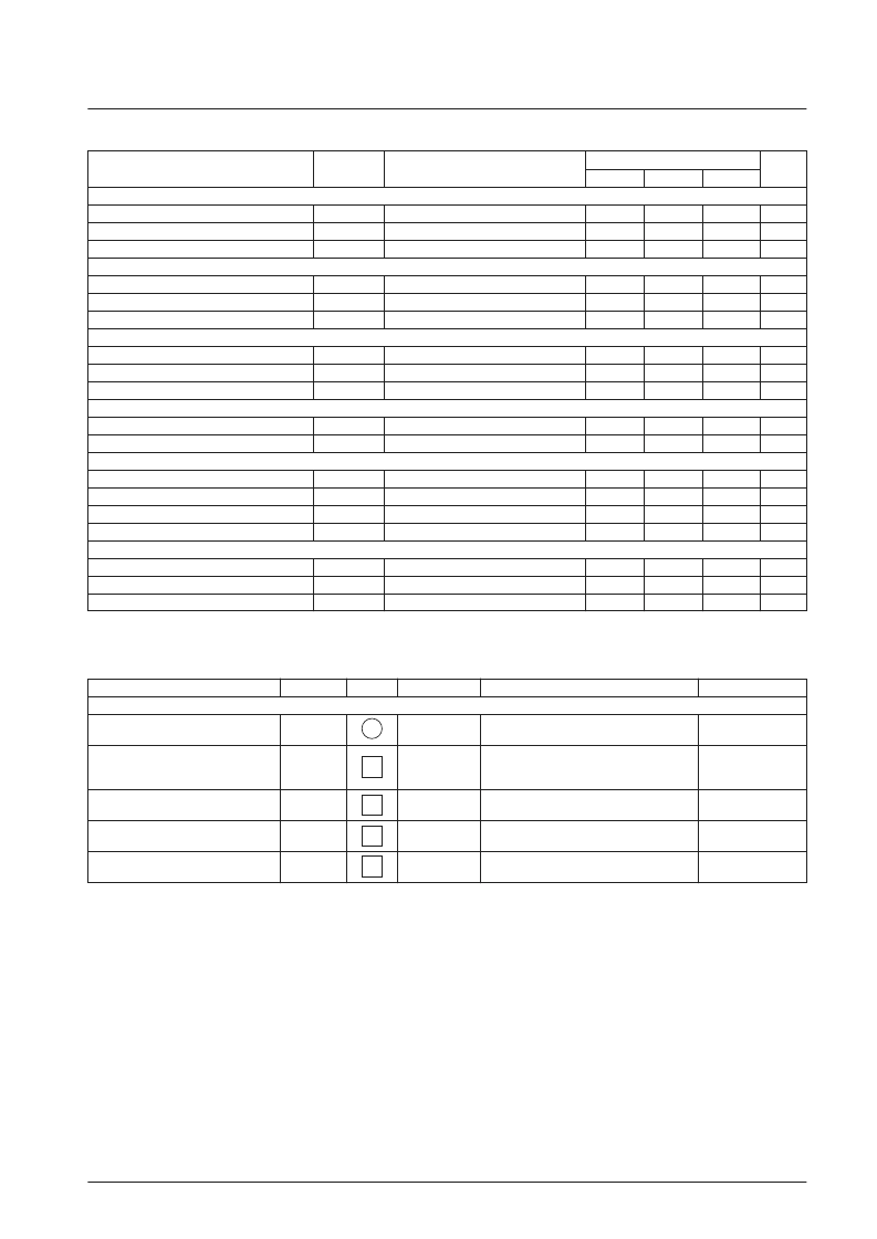
Continued from preceding page.
Parameter
Symbol
Conditions
Ratings
Unit
min
typ
max
[Horizontal Size Adjustment]
East/west DC voltage @16
EWdc16
EW
DC
: 10000
EW
DC
: 00000
EW
DC
: 11111
3.60
4.00
4.40
Vdc
East/west DC voltage @0
EWdc0
2.70
3.05
3.40
Vdc
East/west DC voltage @31
EWdc31
4.80
5.10
5.40
Vdc
[Pin cushion Distortion Correction]
East/west parabola amplitude @8
EWamp8
EW
AMP
: 1000
EW
AMP
: 0000
EW
AMP
: 1111
0.58
0.73
0.88
Vp-p
East/west parabola amplitude @0
EWamp0
0.15
0.30
0.45
Vp-p
East/west parabola amplitude @15
EWamp15
0.95
1.15
1.35
Vp-p
[Trapezoidal Distortion Correction]
East/west parabola tilt @8
EWtilt4
EW
TILT
: 1000
EW
TILT
: 0000
EW
TILT
: 1111
–0.14
0
+0.14
V
East/west parabola tilt @0
EWtilt0
–0.37
–0.23
–0.09
V
East/west parabola tilt @15
EWtilt7
0.09
0.23
0.37
V
[Corner Distortion Correction]
East/west parabola corner, top
EWcorTOP
COR
TOP
: 111-000
COR
BOTTOM
: 111-000
0.15
0.25
0.35
V
East/west parabola corner, bottom
EWcorTOP
0.15
0.25
0.35
V
[Sandcastle Output]
Burst gate pulse peak value
V
BGP
Td
BGP
PW
BGP
V
BLK
5.0
5.7
6.5
V
Burst gate pulse phase
4.6
5.1
5.6
μs
Burst gate pulse width
2.35
2.85
3.35
μs
Blanking pulse peak value
3.4
3.9
4.4
V
[D/A Converter Output]
Pin 30 D/A converter voltage @0
V
DAC
0
V
DAC
8
V
DAC
15
+B TRIM : 0000
2.75
3.00
3.25
V
Pin 30 D/A converter voltage @8
+B TRIM : 1000
3.15
3.40
3.65
V
Pin 30 D/A converter voltage @15
+B TRIM : 1111
3.55
3.80
4.05
V
Circuit Voltage and Current Test Conditions
at Ta = 25°C, V
CC
= V
2
= V
17
= V
32
= V
60
= 7.6 V, I
CC
= I
24
= 24 mA
Parameter
Symbol
Test point
Input signal
Test procedure
Bus condition
[Circuit Voltage and Current]
Horizontal supply voltage
IF current drain (pin 2)
Vertical current drain (pin 17)
Video, chrominance, current drain
(pin 32)
FM power supply current (pin 60)
HV
CC
I
2
(IFI
CC
)
I
17
(DEFI
CC
)
I
32
(YCV
CC
)
I
60
(FMV
CC
)
No signal
No signal
Apply a 24-mA current to pin 24 and measure
the voltage on pin 24 at that time.
Apply 7.6 V to pin 2 and measure the DC
current (in mA) that flows into the IC.
(With 5 V applied to the IF AGC)
Apply 7.6 V to pin 17 and measure the DC
current (in mA) that flows into the IC.
Apply 7.6 V to pin 32 and measure the DC
current (in mA) that flows into the IC.
Apply 7.6 V to pin 60 and measure the DC
current (in mA) that flows into the IC.
Initial
Initial
Initial
Initial
Initial
24
2
17
32
60
相關(guān)PDF資料 |
PDF描述 |
|---|---|
| LA7620 | Color TV Video, Chroma, Deflection Circuit |
| LA7625 | Video, Chroma and Deflection Circuit for Color Television Sets |
| LA7629 | Color TV/Video,Chroma,Deflection Circuit |
| LA7640N | Chroma Circuit for SECAM-system Color Television Sets |
| LA7642N | SECAM Format Color TV Chrominance Circuit |
相關(guān)代理商/技術(shù)參數(shù) |
參數(shù)描述 |
|---|---|
| LA7620 | 制造商:SANYO 制造商全稱:Sanyo Semicon Device 功能描述:Color TV Video, Chroma, Deflection Circuit |
| LA7621 | 制造商:Panasonic Industrial Company 功能描述:IC |
| LA7625 | 制造商:SANYO 制造商全稱:Sanyo Semicon Device 功能描述:Video, Chroma and Deflection Circuit for Color Television Sets |
| LA7626 | 制造商:SANYO 制造商全稱:Sanyo Semicon Device 功能描述:Video, Chroma and Deflection Circuit for Color Television Sets |
| LA7629 | 制造商:SANYO 制造商全稱:Sanyo Semicon Device 功能描述:Color TV/Video,Chroma,Deflection Circuit |
發(fā)布緊急采購,3分鐘左右您將得到回復(fù)。