- 您現(xiàn)在的位置:買(mǎi)賣(mài)IC網(wǎng) > PDF目錄385400 > HT48RA3 (Holtek Semiconductor Inc.) 8-Bit Remote Type OTP MCU PDF資料下載
參數(shù)資料
| 型號(hào): | HT48RA3 |
| 廠商: | Holtek Semiconductor Inc. |
| 英文描述: | 8-Bit Remote Type OTP MCU |
| 中文描述: | 8位單片機(jī)的遠(yuǎn)程型檢察官辦公室 |
| 文件頁(yè)數(shù): | 3/36頁(yè) |
| 文件大小: | 245K |
| 代理商: | HT48RA3 |
第1頁(yè)第2頁(yè)當(dāng)前第3頁(yè)第4頁(yè)第5頁(yè)第6頁(yè)第7頁(yè)第8頁(yè)第9頁(yè)第10頁(yè)第11頁(yè)第12頁(yè)第13頁(yè)第14頁(yè)第15頁(yè)第16頁(yè)第17頁(yè)第18頁(yè)第19頁(yè)第20頁(yè)第21頁(yè)第22頁(yè)第23頁(yè)第24頁(yè)第25頁(yè)第26頁(yè)第27頁(yè)第28頁(yè)第29頁(yè)第30頁(yè)第31頁(yè)第32頁(yè)第33頁(yè)第34頁(yè)第35頁(yè)第36頁(yè)

Absolute Maximum Ratings
Supply Voltage...........................V
SS
0.3V to V
SS
+5.5V
Storage Temperature............................ 50 C to 125 C
Input Voltage..............................V
SS
0.3V to V
DD
+0.3V
Operating Temperature........................... 40 C to 85 C
Note: These are stress ratings only. Stresses exceeding the range specified under Absolute Maximum Ratings may
cause substantial damage to the device. Functional operation of this device at other conditions beyond those
listed in the specification is not implied and prolonged exposure to extreme conditions may affect device reliabil-
ity.
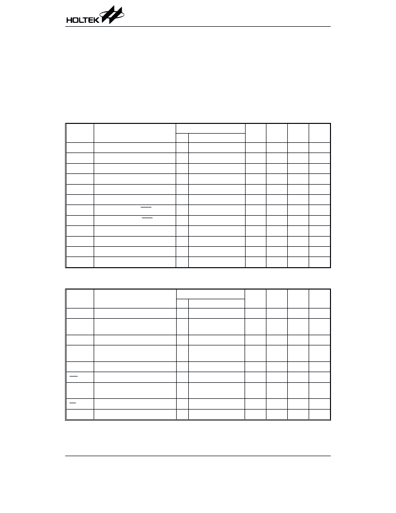
D.C. Characteristics
Ta=25 C
Symbol
Parameter
Test Conditions
Min.
Typ.
Max.
Unit
V
DD
Conditions
V
DD
Operating Voltage
2.2
3.6
V
I
DD
Operating Current
3V
No load, f
SYS
=4MHz
3
5
mA
I
STB1
Standby Current (WDT Enabled)
3V
No load, system HALT
5
10
A
I
STB2
Standby Current (WDT Disabled)
3V
No load, system HALT
0.1
1
A
V
IL1
Input Low Voltage for I/O Ports
0
0.3V
DD
V
V
IH1
Input High Voltage for I/O Ports
0.7V
DD
V
DD
V
V
IL2
Input Low Voltage (RES Ports)
0
0.4V
DD
V
V
IH2
Input High Voltage (RES Ports)
0.9V
DD
V
DD
V
I
OL
I/O Port Sink Current
3V
V
OL
=0.1V
DD
5
10
mA
I
OH1
I/O Port Source Current
3V
V
OH
=0.9V
DD
2
5
mA
I
OH2
I/O Port Source Current
3V
V
OH
=0.8V
DD
4
8
mA
R
PH
Pull-high Resistance
3V
40
60
80
k
A.C. Characteristics
Ta=25 C
Symbol
Parameter
Test Conditions
Min.
Typ.
Max.
Unit
V
DD
Conditions
f
SYS
System Clock
3V
400
4000
kHz
f
TIMER
Timer I/P Frequency
(TMR0/TMR1)
3V
50% duty
0
4000
kHz
t
WDTOSC
Watchdog Oscillator
3V
45
90
180
s
t
WDT1
Watchdog Time-out Period
(WDT OSC)
3V
WithoutWDTprescaler
11.5
23
46
ms
t
WDT2
WatchdogTime-outPeriod(f
SYS
/4) 3V
WithoutWDTprescaler
1024
t
SYS
t
RES
External Reset Low Pulse Width
1
s
t
SST
System Start-up Timer Period
Power-up, reset or
wake-up from HALT
1024
t
SYS
t
INT
Interrupt Pulse Width
1
s
t
ACC
Data ROM Access Time
1
s
Note: t
SYS
=1/(f
SYS
)
HT48RA3
Rev. 1.20
3
May 12, 2003
相關(guān)PDF資料 |
PDF描述 |
|---|---|
| HT48RB8 | 8-Bit USB Type OTP MCU |
| HT49C10 | 8-BIT MICROCONTROLLER |
| HT49C30L | HDSP-A101 RED DISPLAY, LED, |
| HT49R30 | DISPLAY 7 SEGMENT |
| HT49R30A-1 | DISPL 7 SEG YELLOW |
相關(guān)代理商/技術(shù)參數(shù) |
參數(shù)描述 |
|---|---|
| HT48RA3_07 | 制造商:HOLTEK 制造商全稱:Holtek Semiconductor Inc 功能描述:Remote Type 8-Bit MCU |
| HT48RA3_09 | 制造商:HOLTEK 制造商全稱:Holtek Semiconductor Inc 功能描述:HT48RA3/HT48CA3 |
| HT48RA5 | 制造商:HOLTEK 制造商全稱:Holtek Semiconductor Inc 功能描述:Remote Type 8-Bit MCU |
| HT48RA5_07 | 制造商:HOLTEK 制造商全稱:Holtek Semiconductor Inc 功能描述:Remote Type 8-Bit MCU |
| HT48RA5_09 | 制造商:HOLTEK 制造商全稱:Holtek Semiconductor Inc 功能描述:Remote Type 8-Bit MCU |
發(fā)布緊急采購(gòu),3分鐘左右您將得到回復(fù)。