- 您現(xiàn)在的位置:買賣IC網(wǎng) > PDF目錄384443 > HS1-82C55ARH-8 (HARRIS SEMICONDUCTOR) Radiation Hardened CMOS Programmable Peripheral Interface PDF資料下載
參數(shù)資料
| 型號: | HS1-82C55ARH-8 |
| 廠商: | HARRIS SEMICONDUCTOR |
| 元件分類: | 微控制器/微處理器 |
| 英文描述: | Radiation Hardened CMOS Programmable Peripheral Interface |
| 中文描述: | 24 I/O, PIA-GENERAL PURPOSE, CDIP40 |
| 文件頁數(shù): | 19/23頁 |
| 文件大小: | 165K |
| 代理商: | HS1-82C55ARH-8 |
988
HS-82C55ARH
Operating Modes
MODE 2 (Strobed Bidirectional Bus I/O)
The functional configuration provides a means for communi-
cating with a peripheral device or structure on a single 8-bit
bus for both transmitting and receiving data (bidirectional
bus I/O). “Handshaking” signals are provided to maintain
proper bus flow discipline similar to MODE 1. Interrupt gen-
eration and enable/disable functions are also available.
Mode 2 Basic Functional Definitions:
Used in Group A only.
One 8-bit, bidirectional bus port (Port A) and a 5-bit control
port (Port C).
Both inputs and outputs are latched.
The 5-bit control port (Port C) is used for control and
status for the 8-bit, bidirectional bus port (Port A).
Bidirectional Bus I/O Control Signal Definition
INTR (Interrupt Request)
A high on this output can be used to interrupt the CPU for
both input or output operations. INTR will be set either by the
rising edge of ACK (INTE1 = 1) or the rising edge of STB
(INTE2 = 1). INTR will be reset by the falling edge of WR (if
previously set by the rising edge or ACK), the falling edge of
RD (if previously set by the rising edge of STB), or the falling
edge of WR when immediately following a low RD pulse or
the falling edge of RD when immediately following a low WR
pulse (if previously set by the rising edges of both ACK and
STB).
Output Operations
OBF (Output Buffer Full)
The OBF output will go “l(fā)ow” to indicate that the CPU has
written data out to Port A.
ACK (Acknowledge)
A “l(fā)ow” on this input enables the tri-state output buffer of Port
A to send out the data. Otherwise, the output buffer will be in
the high impedance state.
INTE 1 (The INTE Flip-Flop Associated with OBF)
Controlled by Bit Set/Reset of PC6.
Input Operations
STB (Strobe Input)
A “l(fā)ow” on this input loads data into the input latch.
IBF (Input Buffer Full F/F)
A “high” on this output indicates that data has been loaded
into the input latch.
INTE 2 (The INTE Flip-Flop Associated with IBF)
Controlled by Bit Set/Reset of PC4.
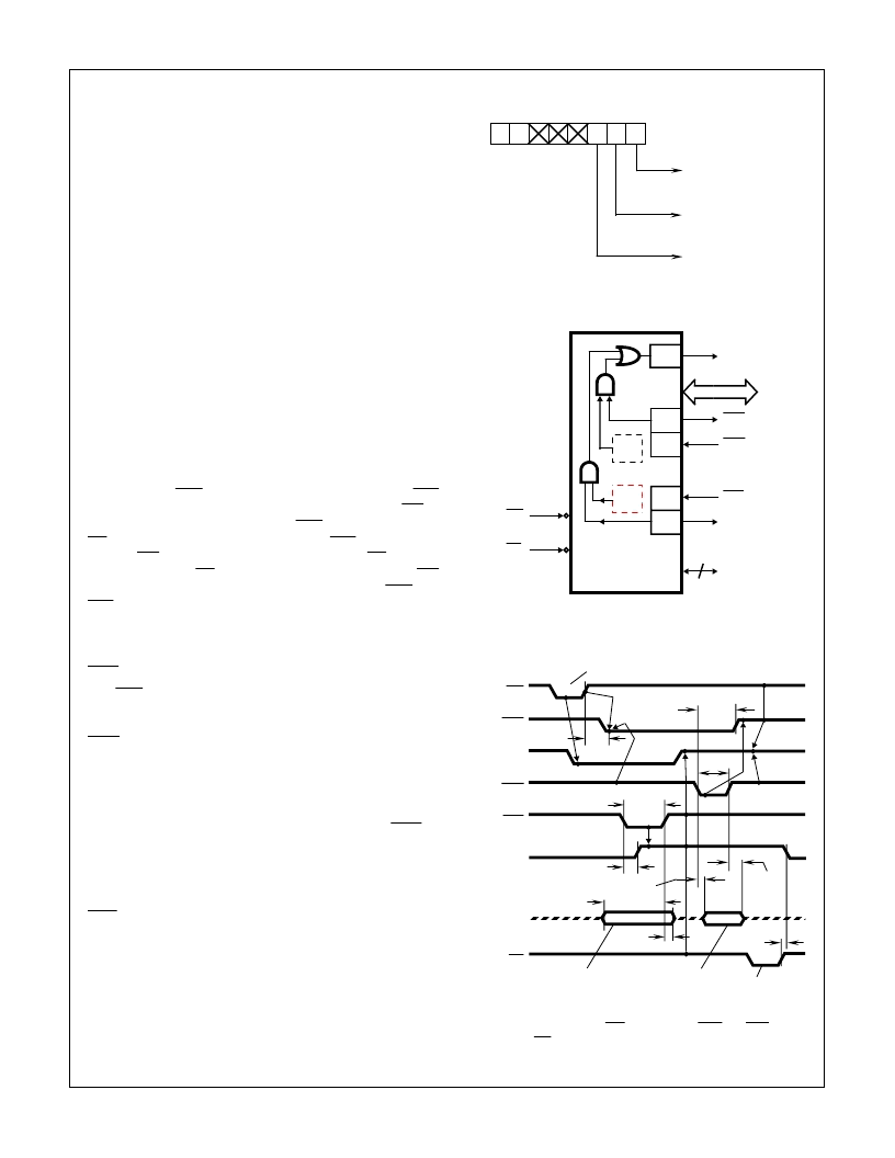
FIGURE 20. MODE CONTROL WORD
FIGURE 21. MODE 2 (BIDIRECTIONAL)
NOTE: Any sequence whereWR occurs beforeACK andSTB occurs
before RD is permissible.
FIGURE 22. MODE 2 (BIDIRECTIONAL)
D7 D6 D5 D4 D3 D2 D1 D0
1
CONTROL WORD
0
1/0 1/0 1/0
PC2 - PC0
1 = INPUT
0 = OUTPUT
PORT B
1 = INPUT
0 = OUTPUT
GROUP B MODE
0 = MODE 0
1 = MODE 1
INTE
2
PC7
PC6
PC3
PC2- PC0
WR
8
STB A
IBF A
INTR A
I/O
3
RD
PC7
PC6
OBF A
ACK A
INTE
1
PA7- PA0
WR
OBF
INTR
ACK
STB
IBF
PERIPHERAL
BUS
RD
DATA FROM PERI-
PHERAL TO
HS-82C55ARH
DATA FROM CPU
TO HS-82C55ARH
TWHOL
TSLIH
TKHOL
TKLKH
DATA FROM
HS-82C55ARH
TO PERIPHERAL
DATA FROM
HS-82C55ARH
TO CPU
TSLSH
TKLPV
TPVSH
TKHPX
TSHPX
TRHIL
Spec Number
518060
相關(guān)PDF資料 |
PDF描述 |
|---|---|
| HS9-2100RH | Radiation Hardened High Frequency Half Bridge Driver |
| HS-2100RH | Radiation Hardened High Frequency Half Bridge Driver(抗輻射高頻半橋N勾道MOSFET驅(qū)動器) |
| HS9-2100RH-8 | Radiation Hardened High Frequency Half Bridge Driver |
| HS9-2100RH-Q | Radiation Hardened High Frequency Half Bridge Driver |
| HS9-22620RH | Rad Hard Dual, Wideband, High Input Impedance Uncompensated Operational Amplifier |
相關(guān)代理商/技術(shù)參數(shù) |
參數(shù)描述 |
|---|---|
| HS1-82C55ARH-Q | 制造商:Intersil Corporation 功能描述:PERIPHERAL INTRFC 40CDIP - Rail/Tube |
| HS1-82C59ARH-8 | 制造商:未知廠家 制造商全稱:未知廠家 功能描述:Interrupt Controller |
| HS1-82C85RH | 制造商:INTERSIL 制造商全稱:Intersil Corporation 功能描述:Radiation Hardened CMOS Static Clock Controller/Generator |
| HS1-82C85RH-8 | 制造商:Intersil Corporation 功能描述:CLOCK CNTRLR/GENERATOR 24PIN SBDIP - Rail/Tube |
| HS1-82C85RH-Q | 制造商:Intersil Corporation 功能描述:CLOCK CNTRLR/GENERATOR 24PIN SBDIP - Rail/Tube |
發(fā)布緊急采購,3分鐘左右您將得到回復(fù)。