- 您現(xiàn)在的位置:買賣IC網(wǎng) > PDF目錄384215 > CLC-CAPT-PCASM PDF資料下載
參數(shù)資料
| 型號: | CLC-CAPT-PCASM |
| 文件頁數(shù): | 7/15頁 |
| 文件大小: | 763K |
| 代理商: | CLC-CAPT-PCASM |
7
http://www.national.com
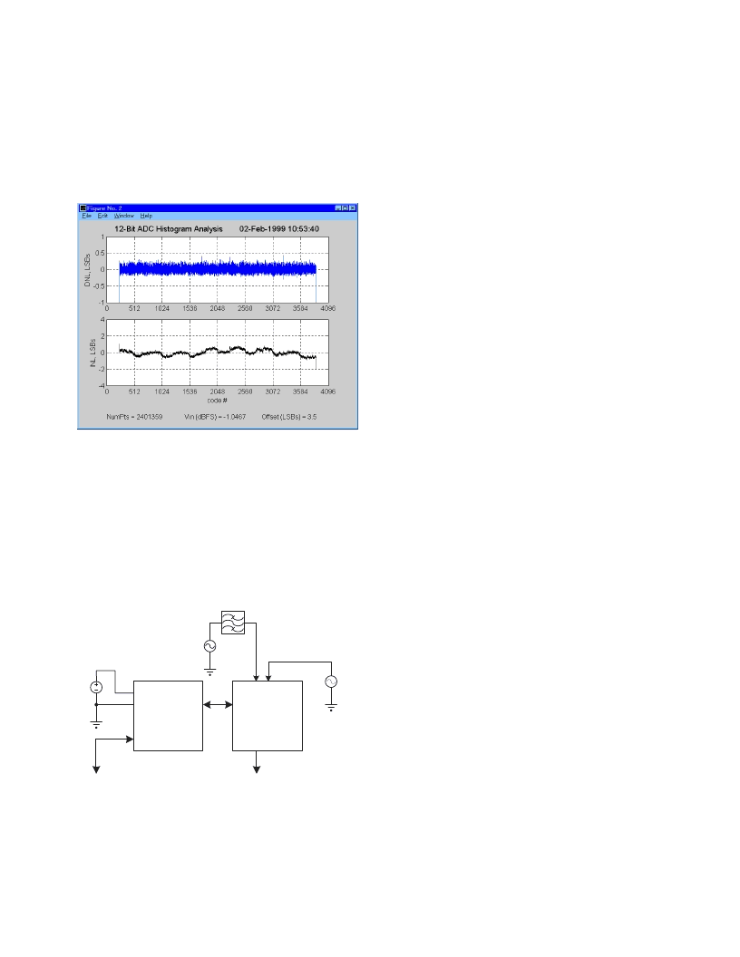
In this example, we have captured data from a 12-Bit
ADC. Remember that the data that we are plotting is the
bin count information. The ADC output codes that were
exercised ranged from code 236 to code 3865. The
maximum count was set to 16384 (with DIP switches 4
and 5 OFF) and for this particular data record the
maximum count was reached at the ADC output code of
3864. To analyze the converter
’
s linearity, you can left
click on the
“DNL_INL”
button, and you will see the
following analysis window:
For more information about this analysis technique,
please refer to Section IV of this document, the com-
ments in the DNL_INL script
fi
le, or the IEEE Standard for
Digitizing Waveform Recorders (IEEE Std 1057-1994).
Section III. Capturing Data from the
Diversity Receiver Chipset (DRCS)
Evaluation Board
Diversity Receiver Chipset Evaluation Setup
Getting Started
To use the Data Capture board to capture data from
National
’
s DRCS Evaluation Board, you will need the
following hardware, software, and documentation.
Several analysis tools are provided in the form of Matlab
scripts. It will prove helpful if the user has some familiarity
with the CLC5902 data sheet and the Diversity Receiver
Evaluation Board User Manual document.
Hardware
1. CLC730093 Data Capture Board.
(CLC-CAPT-PCASM)
2. CLC730090 DRCS Evaluation Board.
(CLC-DRCS-PCASM)
3. DC Power Supply - The DRCS Evaluation and
Capture Board combination require +5V at >1A.
4. An IBM-Compatible Personal Computer running
Windows 95, Windows 98, or Windows NT with a
serial port capable of 115,200 baud.
5. Serial data cable to connect the data capture board
to the PC.
6. Low noise,
fi
ltered, IF Signal source for analog input
to DRCS.
7. OPTIONAL - Low jitter clock source (10 - 16dBm
sinewave) if DRCS crystal oscillator is removed.
Software
1.
“
Capture.exe
”
- Contained in the provided CDROM.
2. Data storage space on PC hard drive (default path &
name =
“
c:\temp\data.dat
”
).
3. Matlab (version 5.1 or higher) to run analysis routines.
Documentation
Applicable product data sheets and user guides can be
found on the provided CD-ROM, with the most current
versions available on our website at:
http://www.national.com/appinfo/wbp
General Description and Program Options
Data from the Diversity Receiver ChipSet (DRCS)
Evaluation Board can be captured from either of its two
serial outputs, its parallel outputs, or its debug outputs.
The serial in-phase and quadrature-phase data can
also be captured simultaneously for quadrature data
analyses. The Data Capture Board always returns 32,768
24-bit words via the serial port as 96K bytes. Each word
is interpreted as a 24-bit two
’
s complement integer and
stored as 32K ASCII words in a user de
fi
ned
fi
le. Each
value is terminated with a carriage return (hexadecimal
0D). When a Diversity Receiver Evaluation Board is
attached to the Data Capture Board, data narrower than
24 bits is aligned to the most signi
fi
cant bit with unused
lower bits set to 0s. Serial data is always 24-bits wide.
Because of the various DRCS data output formats, care
BPF
A
A
C
VCC
GND
OPTIONAL
CLOCK SOURCE
FILTERED
I.F. SOURCE
+5V
VCC
(2A)
10-16dBm
To PC Serial
COMM PORT #1
6
C
DRCS
Evaluation
Board
Data
Capture
Board
Serial I/O
To PC Serial
COMM PORT #2
相關(guān)PDF資料 |
PDF描述 |
|---|---|
| CLC109A8B | Analog Buffer/Voltage Follower |
| CLC109AIB | Analog Buffer/Voltage Follower |
| CLC110A8B | Analog Buffer/Voltage Follower |
| CLC111AIB | Analog Buffer/Voltage Follower |
| CLC114AIB | Analog Buffer/Voltage Follower |
相關(guān)代理商/技術(shù)參數(shù) |
參數(shù)描述 |
|---|---|
| CLCCF1 | 制造商:Dailys Limited 功能描述:LAB COAT M WHITE |
| CL-CD1190 | 制造商:未知廠家 制造商全稱:未知廠家 功能描述:Peripheral IC |
| CL-CD1190-10PC-C | 制造商:未知廠家 制造商全稱:未知廠家 功能描述:Printer Controller |
| CL-CD1283-10QC-D | 制造商:未知廠家 制造商全稱:未知廠家 功能描述:Peripheral (Multifunction) Controller |
| CL-CD1283-10QC-E | 制造商:未知廠家 制造商全稱:未知廠家 功能描述:Peripheral (Multifunction) Controller |
發(fā)布緊急采購,3分鐘左右您將得到回復(fù)。