- 您現(xiàn)在的位置:買賣IC網(wǎng) > PDF目錄375269 > ADV7322 (Analog Devices, Inc.) Multiformat 11-Bit HDTV Video Encoder PDF資料下載
參數(shù)資料
| 型號(hào): | ADV7322 |
| 廠商: | Analog Devices, Inc. |
| 英文描述: | Multiformat 11-Bit HDTV Video Encoder |
| 中文描述: | 多格式11位高清晰度電視視頻編碼器 |
| 文件頁數(shù): | 43/88頁 |
| 文件大小: | 991K |
| 代理商: | ADV7322 |
第1頁第2頁第3頁第4頁第5頁第6頁第7頁第8頁第9頁第10頁第11頁第12頁第13頁第14頁第15頁第16頁第17頁第18頁第19頁第20頁第21頁第22頁第23頁第24頁第25頁第26頁第27頁第28頁第29頁第30頁第31頁第32頁第33頁第34頁第35頁第36頁第37頁第38頁第39頁第40頁第41頁第42頁當(dāng)前第43頁第44頁第45頁第46頁第47頁第48頁第49頁第50頁第51頁第52頁第53頁第54頁第55頁第56頁第57頁第58頁第59頁第60頁第61頁第62頁第63頁第64頁第65頁第66頁第67頁第68頁第69頁第70頁第71頁第72頁第73頁第74頁第75頁第76頁第77頁第78頁第79頁第80頁第81頁第82頁第83頁第84頁第85頁第86頁第87頁第88頁
Preliminary Technical Data
ADV7322
HD ASYNC TIMING MODE
[Subaddress 0x10, Bits 3 and 2]
Rev. PrA | Page 43 of 88
For any input data that does not conform to the standards
selectable in input mode, Subaddress 0x10, asynchronous
timing mode can be used to interface to the ADV7322. Timing
control signals for HSYNC, VSYNC, and BLANK must be
programmed by the user. Macrovision and programmable
oversampling rates are not available in async timing mode.
In async mode, the PLL must be turned off [Subaddress 0x00,
Bit 1 = 1]. Register 0x10 should be programmed to 0x01.
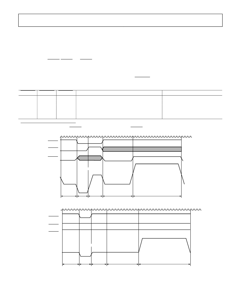
Figure 57 and Figure 58 show examples of how to program the
ADV7322 to accept a high definition standard other than
SMPTE 293M, SMPTE 274M, SMPTE 296M, or ITU-R
BT.1358.
Table 26 must be followed when programming the control signals
in async timing mode. For standards that do not require a trisync
level, P_BLANK must be tied low at all times.
Table 26. Async Timing Mode Truth Table
P_HSYNC P_VSYNC P_BLANK
1
1 —> 0
0
0
0 —> 1
0 —> 1
0 or 1
1
0 or 1
1
0 or 1
Reference
50% point of falling edge of trilevel horizontal sync signal
25% point of rising edge of trilevel horizontal sync signal
50% point of falling edge of trilevel horizontal sync signal
50% start of active video
50% end of active video
Reference in Figure 57
and Figure 58
a
b
c
d
e
0 or 1
0 or 1
0
0 —> 1
1 —> 0
1
When async timing mode is enabled, P_BLANK, Pin 25, becomes an active high input. P_BLANK is set to active low at Address 0x10, Bit 6.
CLK
ACTIVE VIDEO
PROGRAMMABLE
ANALOG
81
66
66
243
1920
HORIZONTAL SYNC
e
d
c
b
a
SET ADDRESS 0x14,
BIT 3 = 1
0
P_HSYNC
P_VSYNC
P_BLANK
Figure 57. Async Timing Mode—Programming Input Control Signals for SMPTE 295M Compatibility
ACTIVE VIDEO
0
1
HORIZONTAL SYNC
e
d
c
b
a
CLK
SET ADDRESS 0x14
BIT 3 = 1
ANALOG OUTPUT
0
P_VSYNC
P_BLANK
P_HSYNC
Figure 58. Async Timing Mode—Programming Input Control Signals for Bilevel Sync Signal
相關(guān)PDF資料 |
PDF描述 |
|---|---|
| ADV7322KSTZ1 | Multiformat 11-Bit HDTV Video Encoder |
| ADV7400 | ADV7402/ADV7400 Multiformat Video Decoders for Advanced TV |
| ADV7400KST-110 | ADV7402/ADV7400 Multiformat Video Decoders for Advanced TV |
| ADV7400KST-140 | ADV7402/ADV7400 Multiformat Video Decoders for Advanced TV |
| ADV7400KST-80 | ADV7402/ADV7400 Multiformat Video Decoders for Advanced TV |
相關(guān)代理商/技術(shù)參數(shù) |
參數(shù)描述 |
|---|---|
| ADV73225709 | 制造商:LG Corporation 功能描述:Frame Assembly |
| ADV73225710 | 制造商:LG Corporation 功能描述:Frame Assembly |
| ADV73225718 | 制造商:LG Corporation 功能描述:Frame Assembly |
| ADV73225719 | 制造商:LG Corporation 功能描述:Frame Assembly |
| ADV73225801 | 制造商:LG Corporation 功能描述:Frame Assembly |
發(fā)布緊急采購,3分鐘左右您將得到回復(fù)。