- 您現(xiàn)在的位置:買賣IC網(wǎng) > PDF目錄223310 > ADM1028ARQZ-REEL7 (ANALOG DEVICES INC) SPECIALTY ANALOG CIRCUIT, PDSO16 PDF資料下載
參數(shù)資料
| 型號: | ADM1028ARQZ-REEL7 |
| 廠商: | ANALOG DEVICES INC |
| 元件分類: | 模擬信號調(diào)理 |
| 英文描述: | SPECIALTY ANALOG CIRCUIT, PDSO16 |
| 封裝: | MO-137AB, QSOP-16 |
| 文件頁數(shù): | 2/16頁 |
| 文件大小: | 379K |
| 代理商: | ADM1028ARQZ-REEL7 |
REV. B
ADM1028
–10–
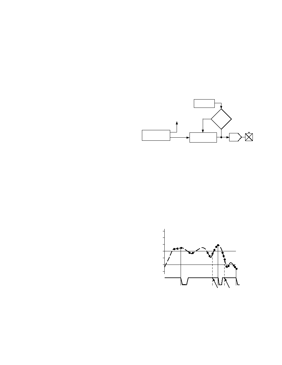
When a new target Fan Speed Value is written to the Fan Speed
Register, the counter begins counting up or down (depending on
whether the current value is greater or less than the target value).
The counter will then count at the rate specified by the ramp rate
bits of the Fan Speed Ramp Register. Once the counter reaches
the target value the counter will stop counting. The FAN_SPD
value is derived from the output of the counter. If a new value is
written to the Fan Speed Register while a ramp function is occur-
ring, the counter may change count direction to reach the new
target value. The operation of
THERM is independent of the fan
speed ramping mechanism. Thus,
THERM will assert immedi-
ately for over-temperature conditions.
FAN SPEED RAMP
RATE REGISTER
COUNTER
(CURRENT SPEED)
DAC
COMPARE
FAN SPEED
REGISTER
RAMP ENABLE
RAMP RATE
UP/DOWN
START/STOP
FAN SPD
Figure 6.
THE ADM1028 INTERRUPT SYSTEM
The ADM1028 has three interrupt outputs,
INT, THERMA
and
THERMB. These have different functions. INT responds
to violations of software programmed temperature limits and its
interrupt sources are maskable, as described in more detail later.
Interrupts and status bits are only set if a limit is exceeded for at
least three consecutive conversions.
Operation of the
INT output is illustrated in Figure 7. Assuming
that the temperature starts off within the programmed limits and
that temperature interrupt sources are not masked,
INT will go
low if the temperature measured by the external sensor goes
outside the programmed high or low temperature limit for the
sensor.
INT also goes low whenever THERM is low.
100 C
90 C
80 C
70 C
60 C
50 C
40 C
INT
TEMP
LOW LIMIT
HIGH LIMIT
THIGH INTERRUPT
LOGIC REARMED
HERE
*
INT CLEARED BY
SOFTWARE
**
Figure 7. Operation of
INT Output
Once the interrupt has been cleared, it will not be reasserted even
if the temperature remains outside the limit previously exceeded.
However,
INT will be rearmed if the temperature falls back within
the set limits for three consecutive conversions. Once the
INT
function has been rearmed, it will then be reasserted once a
limit is exceeded for three consecutive conversions.
FAULT TOLERANT FAN CONTROL
The ADM1028 incorporates a fault tolerant fan control capability
that is tied to operation of the
THERMA, THERMB outputs. It
can override the setting of the analog output and force it to maxi-
mum to give full fan speed in the event of a critical over-temperature
problem, even if, for some reason, this has not been handled by
the system software.
There are two temperature set point registers that will activate the
fault tolerant fan control. One of these limits is programmable
by the user and one is a hardware (read-only) register that will
operate if the user does not program any limit. The fault tolerant fan
control is activated if a limit is exceeded for three or more con-
secutive readings. These limits are separate from the normal
high and low temperature limits for the
INT output, which do
not affect the fault tolerant fan control or
THERM outputs.
A hardware limit of 100
∞C is programmed into the register at
address 18h, for the remote diode Default
THERM limit. This
is the default limit and the analog output will be forced to full-
scale if the remote sensor reads more than 100
∞C. This makes
the fault tolerant fan control fail-safe in that it will operate at
this temperature even if the user has programmed no other limit,
or in the event of a software malfunction. Similarly, the Default
Internal Temp
THERM limit held in register 17h, forces the
analog output full-scale if the ambient temperature measured is
more than 70
∞C.
The user may override the default limits by programming a new
limit into register 14h for the remote sensor and a new limit into
register 13h for the internal sensor. The default value in register
14h is the same as for the read-only register (100
∞C), but it may
be programmed with higher or lower values.
Once registers 13h and 14h have been programmed, or if the
defaults are acceptable, Bit 3 of the configuration register must
be set to “1.” This bit is a write-once bit that can only be writ-
ten to “1,” and it has two effects:
1. It makes the values in registers 13h and 14h the active limits,
and disables read-only registers 17h and 18h.
2. It locks the data into registers 13h and 14h, so that it cannot
be changed until the lock bit is reset, either when
AUXRST
or
RST is asserted, or a Power-On Reset occurs.
Once the hardware override of the analog output is triggered, it
will only return to normal operation after three consecutive
measurements that are 5 degrees lower than the set limit.
Whenever FAN_SPD output is forced to full-scale, the
FAN_OFF
output is negated.
FAN SPEED RAMPING
The ADM1028 device contains a Fan Speed Ramping mecha-
nism that is accomplished using an 8-bit counter and a control
register. On power-up, or an assertion of
RST or AUXRST, the
Fan Speed Register, counter, and Fan Speed Ramp Register are
initialized to 0x00. The fan speed ramping mechanism is disabled
by default and any value written to the Fan Speed Register is
immediately reflected on the FAN_SPD output. Setting Bit 0 of
the Fan Speed Ramp Rate Register enables the ramping mechanism.
The counter is then preloaded with the current value contained
in the Fan Speed Register, which prevents the fan speed from
changing until a new value is written to the Fan Speed Register.
相關(guān)PDF資料 |
PDF描述 |
|---|---|
| ADM1232ARWZ | 1-CHANNEL POWER SUPPLY MANAGEMENT CKT, PDSO16 |
| ADM2223AL5 | FIBER OPTIC ADD/DROP MUX/DEMUX, FC/SPC CONNECTOR |
| ADM322323BB4 | FIBER OPTIC ADD/DROP MUX/DEMUX, SC/APC CONNECTOR |
| ADM322323AL5 | FIBER OPTIC ADD/DROP MUX/DEMUX, FC/SPC CONNECTOR |
| ADP-ED7887/1+ | 1 MHz - 1050 MHz RF/MICROWAVE COMBINER, 3.94 dB INSERTION LOSS |
相關(guān)代理商/技術(shù)參數(shù) |
參數(shù)描述 |
|---|---|
| ADM1029 | 制造商:AD 制造商全稱:Analog Devices 功能描述:Dual PWM Fan Controller and Temperature Monitor for High Availability Systems |
| ADM1029ARQ | 制造商:Rochester Electronics LLC 功能描述:TDM AND FAN CONTROLLER I.C. - Bulk |
| ADM1029ARQ-REEL7 | 制造商:Rochester Electronics LLC 功能描述: 制造商:Analog Devices 功能描述: |
| ADM1029ARQZ | 功能描述:馬達(dá)/運動/點火控制器和驅(qū)動器 +/- 1 C Digital Serial RoHS:否 制造商:STMicroelectronics 產(chǎn)品:Stepper Motor Controllers / Drivers 類型:2 Phase Stepper Motor Driver 工作電源電壓:8 V to 45 V 電源電流:0.5 mA 工作溫度:- 25 C to + 125 C 安裝風(fēng)格:SMD/SMT 封裝 / 箱體:HTSSOP-28 封裝:Tube |
| ADM1029ARQZ-R7 | 功能描述:馬達(dá)/運動/點火控制器和驅(qū)動器 +/- 1 C Digital Serial RoHS:否 制造商:STMicroelectronics 產(chǎn)品:Stepper Motor Controllers / Drivers 類型:2 Phase Stepper Motor Driver 工作電源電壓:8 V to 45 V 電源電流:0.5 mA 工作溫度:- 25 C to + 125 C 安裝風(fēng)格:SMD/SMT 封裝 / 箱體:HTSSOP-28 封裝:Tube |
發(fā)布緊急采購,3分鐘左右您將得到回復(fù)。