- 您現(xiàn)在的位置:買(mǎi)賣(mài)IC網(wǎng) > PDF目錄372950 > XRT73L03IV (EXAR CORP) 3 CHANNEL E3/DS3/STS-1 LINE INTERFCE UNIT PDF資料下載
參數(shù)資料
| 型號(hào): | XRT73L03IV |
| 廠(chǎng)商: | EXAR CORP |
| 元件分類(lèi): | 數(shù)字傳輸電路 |
| 英文描述: | 3 CHANNEL E3/DS3/STS-1 LINE INTERFCE UNIT |
| 中文描述: | DATACOM, PCM TRANSCEIVER, PQFP120 |
| 封裝: | 14 X 20 MM, HEAT SINK, TQFP-120 |
| 文件頁(yè)數(shù): | 43/53頁(yè) |
| 文件大小: | 604K |
| 代理商: | XRT73L03IV |
第1頁(yè)第2頁(yè)第3頁(yè)第4頁(yè)第5頁(yè)第6頁(yè)第7頁(yè)第8頁(yè)第9頁(yè)第10頁(yè)第11頁(yè)第12頁(yè)第13頁(yè)第14頁(yè)第15頁(yè)第16頁(yè)第17頁(yè)第18頁(yè)第19頁(yè)第20頁(yè)第21頁(yè)第22頁(yè)第23頁(yè)第24頁(yè)第25頁(yè)第26頁(yè)第27頁(yè)第28頁(yè)第29頁(yè)第30頁(yè)第31頁(yè)第32頁(yè)第33頁(yè)第34頁(yè)第35頁(yè)第36頁(yè)第37頁(yè)第38頁(yè)第39頁(yè)第40頁(yè)第41頁(yè)第42頁(yè)當(dāng)前第43頁(yè)第44頁(yè)第45頁(yè)第46頁(yè)第47頁(yè)第48頁(yè)第49頁(yè)第50頁(yè)第51頁(yè)第52頁(yè)第53頁(yè)
á
XRT73L00
E3/DS3/STS-1 LINE INTERFACE UNIT
REV. 1.2.0
40
If the XRT73L00 is operating in the HOST Mode:
Access the Microprocessor Serial Interface and write
a “1” into the LLB bit-field and a “0” into the RLB bit-
field in Command Register 4.
If the XRT73L00 is operating in the Hardware
Mode:
The LLB input pin (pin 14) must be set to “High” and
the RLB input pin (pin 15) must be set to “Low”.
N
OTES
:
1. The Analog Local Loop-Back Mode does not work
if the transmitter is turned off via the TXOFF fea-
ture.
2. The XRT73L00 automatically Declares an LOS
Condition anytime it has been configured to oper-
ate in either the Analog Local Loop-Back or Digital
Local Loop-Back Modes. Consequently, the MUT-
ing -upon -LOS must be disabled prior to configur-
ing the device to operate in either of these local
Loop-Back modes.
T
HE
D
IGITAL
L
OCAL
L
OOP
-B
ACK
M
ODE
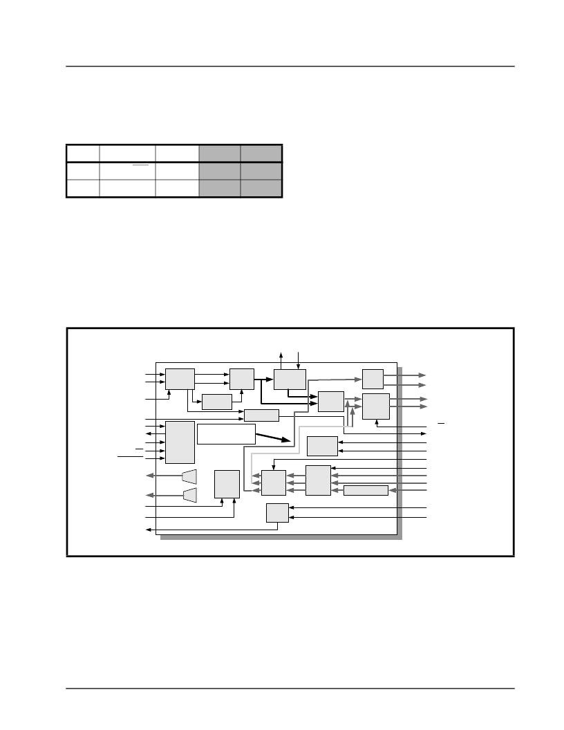
When the XRT73L00 is configured to operate in the
Digital Local Loop-Back Mode, it ignores any signals
that are input to the RTIP and RRING input pins. The
Transmitting Terminal Equipment transmits clock and
data into the XRT73L00 via the TPDATA, TNDATA
and TCLK input pins. This data is processed through
the Transmit Clock Duty Cycle Adjust PLL and the
HDB3/B3ZS Encoder block and then looped back to
the HDB3/B3ZS Decoder block.
Figure 29 illustrates the path that the data takes when
the chip is configured to operate in the Digital Local
Loop-Back Mode.
4.2
The Digital Local Loop-Back Mode, along with the Tx-
OFF feature, is useful in Redundancy System De-
sign. These two features permit the system to exe-
cute some diagnostic tests in the Back-up Line Card
without transmitting data onto the line and interfering
with the DS3/E3/STS-1 traffic from the Primary Line
Card.
The XRT73L00 can be configured to operate in the
Digital Local Loop-Back Mode by employing either
one of the following two-steps.
A. If the XRT73L00 is operating in the HOST
Mode
Access the Microprocessor Serial Interface and write
a “1” into both the LLB and RLB bit-fields in Com-
mand Register 4.
COMMAND REGISTER CR4 (ADDRESS = 0X04)
D4
D3
D2
D1
D0
X
STS-1/DS3
E3
LLB
RLB
X
X
X
1
0
F
IGURE
29. T
HE
D
IGITAL
L
OCAL
L
OOP
-B
ACK
PATH
IN
THE
XRT73L00
AGC/
Equalizer
Peak
Detector
LOS Detector
Slicer
Clock
Recovery
Data
Recovery
Invert
Loop MUX
HDB3/
B3ZS
Decoder
LOSTHR
SDI
SDO/LCV
SCLK
CS
REGRESET
RTIP
RRING
REQDIS
RCLK1
RCLK2
RPOS
RNEG
DR/SR
RLOS
LLB
RLB
ENDECDIS
TAOS
TPDATA
TNDATA
TCLK
RLOL EXCLK
Device
Monitor
MTIP
MRING
Transmit
Logic
Duty Cycle Adjust
TXLEV
TXOFF
DMO
TTIP
TRING
Pulse
Shaping
HDB3/
B3ZS
Encoder
Serial
Processor
Interface
Digital Local
Loop-Back Path
相關(guān)PDF資料 |
PDF描述 |
|---|---|
| XRT73LC00 | E3/DS3/STS-1 LINE INTERFACE UNIT |
| XRT73LC00IV | E3/DS3/STS-1 LINE INTERFACE UNIT |
| XRT73L00 | E3/DS3/STS-1 LINE INTERFACE UNIT |
| XRT73L00A | E3/DS3/STS-1 LINE INTERFACE UNIT |
| XRT73L00AIV | E3/DS3/STS-1 LINE INTERFACE UNIT |
相關(guān)代理商/技術(shù)參數(shù) |
參數(shù)描述 |
|---|---|
| XRT73L03IVS | 制造商:未知廠(chǎng)家 制造商全稱(chēng):未知廠(chǎng)家 功能描述:Telecommunication IC |
| XRT73L04A | 制造商:EXAR 制造商全稱(chēng):EXAR 功能描述:4 CHANNEL DS3/E3/STS-1 LINE INTERFACE UNIT |
| XRT73L04AIV | 制造商:EXAR 制造商全稱(chēng):EXAR 功能描述:4 CHANNEL DS3/E3/STS-1 LINE INTERFACE UNIT |
| XRT73L04B | 制造商:EXAR 制造商全稱(chēng):EXAR 功能描述:4 CHANNEL DS3/E3/STS-1 LINE INTERFACE UNIT |
| XRT73L04BES | 功能描述:網(wǎng)絡(luò)控制器與處理器 IC RoHS:否 制造商:Micrel 產(chǎn)品:Controller Area Network (CAN) 收發(fā)器數(shù)量: 數(shù)據(jù)速率: 電源電流(最大值):595 mA 最大工作溫度:+ 85 C 安裝風(fēng)格:SMD/SMT 封裝 / 箱體:PBGA-400 封裝:Tray |
發(fā)布緊急采購(gòu),3分鐘左右您將得到回復(fù)。