- 您現(xiàn)在的位置:買賣IC網(wǎng) > PDF目錄359452 > VV5410 (意法半導(dǎo)體) Mono and Colour Digital Video CMOS Image Sensors PDF資料下載
參數(shù)資料
| 型號(hào): | VV5410 |
| 廠商: | 意法半導(dǎo)體 |
| 英文描述: | Mono and Colour Digital Video CMOS Image Sensors |
| 中文描述: | 莫諾和數(shù)字視頻彩色CMOS圖像傳感器 |
| 文件頁(yè)數(shù): | 82/105頁(yè) |
| 文件大小: | 489K |
| 代理商: | VV5410 |
第1頁(yè)第2頁(yè)第3頁(yè)第4頁(yè)第5頁(yè)第6頁(yè)第7頁(yè)第8頁(yè)第9頁(yè)第10頁(yè)第11頁(yè)第12頁(yè)第13頁(yè)第14頁(yè)第15頁(yè)第16頁(yè)第17頁(yè)第18頁(yè)第19頁(yè)第20頁(yè)第21頁(yè)第22頁(yè)第23頁(yè)第24頁(yè)第25頁(yè)第26頁(yè)第27頁(yè)第28頁(yè)第29頁(yè)第30頁(yè)第31頁(yè)第32頁(yè)第33頁(yè)第34頁(yè)第35頁(yè)第36頁(yè)第37頁(yè)第38頁(yè)第39頁(yè)第40頁(yè)第41頁(yè)第42頁(yè)第43頁(yè)第44頁(yè)第45頁(yè)第46頁(yè)第47頁(yè)第48頁(yè)第49頁(yè)第50頁(yè)第51頁(yè)第52頁(yè)第53頁(yè)第54頁(yè)第55頁(yè)第56頁(yè)第57頁(yè)第58頁(yè)第59頁(yè)第60頁(yè)第61頁(yè)第62頁(yè)第63頁(yè)第64頁(yè)第65頁(yè)第66頁(yè)第67頁(yè)第68頁(yè)第69頁(yè)第70頁(yè)第71頁(yè)第72頁(yè)第73頁(yè)第74頁(yè)第75頁(yè)第76頁(yè)第77頁(yè)第78頁(yè)第79頁(yè)第80頁(yè)第81頁(yè)當(dāng)前第82頁(yè)第83頁(yè)第84頁(yè)第85頁(yè)第86頁(yè)第87頁(yè)第88頁(yè)第89頁(yè)第90頁(yè)第91頁(yè)第92頁(yè)第93頁(yè)第94頁(yè)第95頁(yè)第96頁(yè)第97頁(yè)第98頁(yè)第99頁(yè)第100頁(yè)第101頁(yè)第102頁(yè)第103頁(yè)第104頁(yè)第105頁(yè)
VV5410 & VV6410
Serial Control Bus
cd5410-6410f-3-0.fm
Commercial in confidence
82/105
9.6
This section gives guidelines on the basic operations to read data from and write data to the serial interface.
Types of messages
The serial interface supports variable length messages. A message may contain no data bytes, one data byte or many data
bytes. This data can be written to or read from common or different locations within the sensor. The range of instructions
available are detailed below.
Write no data byte, only sets the index for a subsequent read message.
Single location data write or read for monitoring (real time control)
Multiple location read or write for fast information transfers.
Examples of these operations are given below. A full description of the internal registers is given in the previous section. For all
examples the slave address used is 32
10
for writing and 33
10
for reading. The write address includes the read/write bit (the lsb)
set to zero while this bit is set in the read address.
9.6.1
When a random value is written to the sensor, the message will look like this:
Single location, single data write.
In this example, the fineHexposure register (index = 32
10
) is set to 85
10
. The r/w bit is set to zero for writing and the
of the index byte) is set to zero to disable automatic increment of the index after writing the value. The address index is preserved
and may be used by a subsequent read. The write message is terminated with a stop condition from the master.
bit (msbit
9.6.2
A read message always contains the index used to get the first byte.
Single location, single data read.
This example assumes that a write message has already taken place and the residual index value is 32
10
. A value of 85
from the fineHexposure register. Note that the read message is terminated with a negative acknowledge (A) from the master: it is
not guaranteed that the master will be able to issue a stop condition at any other time during a read message. This is because if
the data sent by the slave is all zeros, the sdaline cannot rise, which is part of the stop condition.
is read
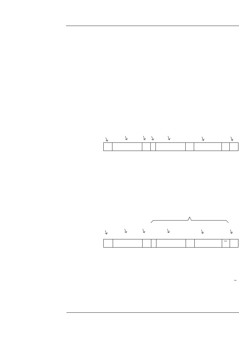
Figure 38 : Single location, single write.
S
32
10
A
0
32
10
A
85
10
A
P
Start
Device
address
Ack
Index
Data
Stop
Inc
Figure 39 : Single location, single read.
S
33
10
A
0
32
10
A
85
10
A
P
Start
Device
address
Ack
Index
Data
Stop
Master reads from slave, acknowledging
each byte
相關(guān)PDF資料 |
PDF描述 |
|---|---|
| VV5430C001 | Monochrome Analog Output CMOS Image Sensors |
| VV5430 | Integrated CMOS Image Sensor with support for ADC and external control via serial interface |
| VV6410C036 | DUAL-MODE DIGITAL CAMERA CHIPSET |
| VV6410 | XTAL MTL T/H HC49/US |
| VV6444 | Low Cost Digital Camera (LCDC) Chipset |
相關(guān)代理商/技術(shù)參數(shù) |
參數(shù)描述 |
|---|---|
| VV5410C036 | 制造商:STMicroelectronics 功能描述:IMAGE SENSOR MONOCHROME CMOS 352X288PIXELS 36CLCC - Bulk |
| VV5430 | 制造商:未知廠家 制造商全稱:未知廠家 功能描述:Integrated CMOS Image Sensor with support for ADC and external control via serial interface |
| VV5430C001 | 制造商:STMICROELECTRONICS 制造商全稱:STMicroelectronics 功能描述:Monochrome Analog Output CMOS Image Sensors |
| VV5501C001 | 功能描述:視頻 IC Monochrome Sensor RoHS:否 制造商:Fairchild Semiconductor 工作電源電壓:5 V 電源電流:80 mA 最大工作溫度:+ 85 C 封裝 / 箱體:TSSOP-28 封裝:Reel |
| VV5F3-30-041 | 制造商:SMC Corporation of America 功能描述:Manifold Base for VF series, base mt, 1/4 inch |
發(fā)布緊急采購(gòu),3分鐘左右您將得到回復(fù)。