- 您現(xiàn)在的位置:買賣IC網(wǎng) > PDF目錄359352 > VCT3801A (MICRONAS SEMICONDUCTOR HOLDING AG) Video/Controller/Teletext IC Family PDF資料下載
參數(shù)資料
| 型號(hào): | VCT3801A |
| 廠商: | MICRONAS SEMICONDUCTOR HOLDING AG |
| 英文描述: | Video/Controller/Teletext IC Family |
| 中文描述: | 視頻/控制/圖文電視IC系列 |
| 文件頁數(shù): | 30/172頁 |
| 文件大小: | 2243K |
| 代理商: | VCT3801A |
第1頁第2頁第3頁第4頁第5頁第6頁第7頁第8頁第9頁第10頁第11頁第12頁第13頁第14頁第15頁第16頁第17頁第18頁第19頁第20頁第21頁第22頁第23頁第24頁第25頁第26頁第27頁第28頁第29頁當(dāng)前第30頁第31頁第32頁第33頁第34頁第35頁第36頁第37頁第38頁第39頁第40頁第41頁第42頁第43頁第44頁第45頁第46頁第47頁第48頁第49頁第50頁第51頁第52頁第53頁第54頁第55頁第56頁第57頁第58頁第59頁第60頁第61頁第62頁第63頁第64頁第65頁第66頁第67頁第68頁第69頁第70頁第71頁第72頁第73頁第74頁第75頁第76頁第77頁第78頁第79頁第80頁第81頁第82頁第83頁第84頁第85頁第86頁第87頁第88頁第89頁第90頁第91頁第92頁第93頁第94頁第95頁第96頁第97頁第98頁第99頁第100頁第101頁第102頁第103頁第104頁第105頁第106頁第107頁第108頁第109頁第110頁第111頁第112頁第113頁第114頁第115頁第116頁第117頁第118頁第119頁第120頁第121頁第122頁第123頁第124頁第125頁第126頁第127頁第128頁第129頁第130頁第131頁第132頁第133頁第134頁第135頁第136頁第137頁第138頁第139頁第140頁第141頁第142頁第143頁第144頁第145頁第146頁第147頁第148頁第149頁第150頁第151頁第152頁第153頁第154頁第155頁第156頁第157頁第158頁第159頁第160頁第161頁第162頁第163頁第164頁第165頁第166頁第167頁第168頁第169頁第170頁第171頁第172頁
VCT 38xxA
ADVANCE INFORMATION
30
Micronas
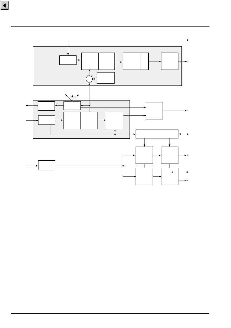
Fig. 2–24:
Deflection processing block diagram
2.12.4.Vertical and East/West Deflection
The calculations of the vertical and East/West deflec-
tion waveforms is done by the internal Fast Processor
(FP). The algorithm uses a chain of accumulators to
generate the required polynomial waveforms. To pro-
duce the deflection waveforms, the accumulators are
initialized at the beginning of each field. The initializa-
tion values must be computed by the TV control pro-
cessor and are written to the front-end once. The
waveforms are described as polynomials in x, where x
varies from 0 to 1 for one field.
P: a
+
b
(x-0.5) +
c
(x-0.5)
2
+
d
(x-0.5)
3
+
e
(x-0.5)
4
The initialization values for the accumulators a0..a3 for
vertical deflection and a0..a4 for East/West deflection
are 12-bit values.
Fig. 2–25 shows several vertical and East/West deflec-
tion waveforms. The polynomial coefficients are also
stated.
In order to get a faster vertical retrace timing, the out-
put impedance of the vertical D/A-converter can be
reduced by 50 % during the retrace.
2.12.5.EHT Compensation
The vertical waveform can be scaled according to the
average beam current. This is used to compensate the
effects of electric high-tension changes due to beam
current variations. EHT compensation for East/West
deflection is done with an offset corresponding to the
average beam current.
Phase
Comparator
&
Low-pass
PLL2
E/W
correction
Sawtooth
PWM
15-bit
EW
VERT
VPROT
PWM
15-bit
DCO
Front
Sync
Interface
FSY
VDATA
Main
Sync
Generator
Vertical
Data
Phase
Comparator
&
Low-pass
PLL3
1:64
&
Output
Stage
HFLB
HOUT
DCO
Display
Timing
Line
Counter
blanking, clamping, etc.
Clock & Control
Sinewave
Generator
&
DAC
LPF
MSY
vertical reset
Skew
Measure-
ment
Angle &
Bow
+
VERTQ
Sync
Generation
INTLC
相關(guān)PDF資料 |
PDF描述 |
|---|---|
| VCU2133 | High-Speed coder/decoder IC |
| VCX2150A | Surface mount 15.88 mm SQ (.625 SQ) |
| VCX2154A | Surface mount 15.88 mm SQ (.625 SQ) |
| VCXO-105N | VCXO |
| VCXO-199 | VCXO |
相關(guān)代理商/技術(shù)參數(shù) |
參數(shù)描述 |
|---|---|
| VCT3802A | 制造商:MICRONAS 制造商全稱:MICRONAS 功能描述:Video/Controller/Teletext IC Family |
| VCT3803A | 制造商:MICRONAS 制造商全稱:MICRONAS 功能描述:Video/Controller/Teletext IC Family |
| VCT3804A | 制造商:MICRONAS 制造商全稱:MICRONAS 功能描述:Video/Controller/Teletext IC Family |
| VCT3811A | 制造商:MICRONAS 制造商全稱:MICRONAS 功能描述:Video/Controller/Teletext IC Family |
| VCT3831A | 制造商:MICRONAS 制造商全稱:MICRONAS 功能描述:Video/Controller/Teletext IC Family |
發(fā)布緊急采購(gòu),3分鐘左右您將得到回復(fù)。