- 您現(xiàn)在的位置:買賣IC網(wǎng) > PDF目錄384021 > TMS320AV120 (Texas Instruments, Inc.) MPEG Audio Decoder(MPEG音頻譯碼器) PDF資料下載
參數(shù)資料
| 型號(hào): | TMS320AV120 |
| 廠商: | Texas Instruments, Inc. |
| 英文描述: | MPEG Audio Decoder(MPEG音頻譯碼器) |
| 中文描述: | MPEG音頻解碼器(的MPEG音頻譯碼器) |
| 文件頁(yè)數(shù): | 8/17頁(yè) |
| 文件大小: | 380K |
| 代理商: | TMS320AV120 |
第1頁(yè)第2頁(yè)第3頁(yè)第4頁(yè)第5頁(yè)第6頁(yè)第7頁(yè)當(dāng)前第8頁(yè)第9頁(yè)第10頁(yè)第11頁(yè)第12頁(yè)第13頁(yè)第14頁(yè)第15頁(yè)第16頁(yè)第17頁(yè)
TMS320AV120
MPEG AUDIO DECODER
SCSS014A – MARCH 1994 – REVISED JANUARY 1996
8
POST OFFICE BOX 655303
DALLAS, TEXAS 75265
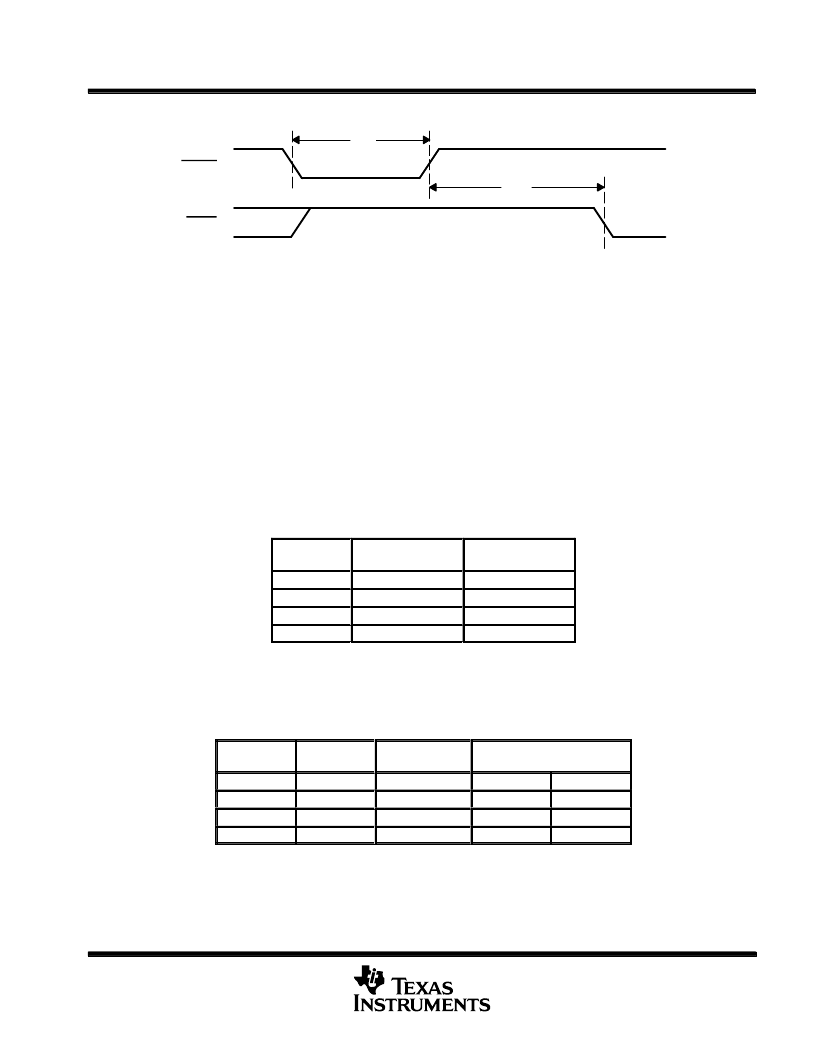
reset sequence (continued)
tw3
tpd2
RESET
SREQ
Figure 5. Reset Timing
input processor
The input processor decodes the header and prepares the audio data for the arithmetic unit. If synchronization
is lost or an error is found in the header or during the CRC check (if the bit stream is protected), the PCM output
for that frame is muted. The status register is updated to signal a synchronization or CRC error.
PCM output interface
The decoded audio data is output in serial PCM-data format on PCMOUT. The data is output with the most
significant bit first. PCM data can be latched on the rising edge of the serial PCM output clock (SCLK). The data
output on PCMOUT alternates between the two channels as designated by LRCLK. If the input data stream is
monophonic, the same PCM data is output on both channels. As shown in Table 1, if the input data stream is
dual channel (two independent channels), the channel(s) output depends on the setting of OMODE.
Table 1. OMODE1 and OMODE0 Functional Summary
áááááááááááááá
áááááááááááááá
áááááááááááááá
áááááááááááááá
OUTPUT
OUTPUT
áááááááááááááá
00
Channel 0
Channel 1
áááááááááááááá
The PCMSEL terminals select the ratio of PCMCLK to SCLK and the number of bits per PCM word. If the PCM
word size is 24, the first 6 bits are zeros followed by an 18-bit PCM value. Output precision and PCM word length
are selected by the PCMSEL terminals as shown in Table 2.
Table 2. PCMSEL1 and PCMSEL2 Functional Summary
ááááááááááááááááááá
ááááááááááááááááááá
ááááááááááááááááááá
ááááááááááááááááááá
ááááááááááááááááááá
PCM
ááááááááááááááááááá
相關(guān)PDF資料 |
PDF描述 |
|---|---|
| TMS320AV220 | Video CD MPEG Decoder(視頻CD MPEG編碼器) |
| TMS320AV410 | Digital NTSC/PAL Encoder(數(shù)字NTSC/PAL編碼器) |
| TMS320AV411 | Digital NTSC/PAL Encoder(數(shù)字NTSC/PAL編碼器) |
| TMS320AV420 | Digital NTSC Encoder(數(shù)字NTSC編碼器) |
| TMS320C6424_1 | Fixed-Point Digital Signal Processor |
相關(guān)代理商/技術(shù)參數(shù) |
參數(shù)描述 |
|---|---|
| TMS320AV120FN | 制造商:未知廠家 制造商全稱:未知廠家 功能描述:Digital Audio Decoder & Support |
| TMS320AV220PCM | 制造商:未知廠家 制造商全稱:未知廠家 功能描述:Audio/Video Decoder for MPEG |
| TMS320AV410 | 制造商:未知廠家 制造商全稱:未知廠家 功能描述:Color Encoder Circuit |
| TMS320AV410PJM | 制造商:Rochester Electronics LLC 功能描述:- Bulk |
| TMS320AV411 | 制造商:未知廠家 制造商全稱:未知廠家 功能描述:Color Encoder Circuit |
發(fā)布緊急采購(gòu),3分鐘左右您將得到回復(fù)。