- 您現(xiàn)在的位置:買賣IC網(wǎng) > PDF目錄384014 > TMC2490A (Fairchild Semiconductor Corporation) Multistandard Digital Video Encoder PDF資料下載
參數(shù)資料
| 型號: | TMC2490A |
| 廠商: | Fairchild Semiconductor Corporation |
| 英文描述: | Multistandard Digital Video Encoder |
| 中文描述: | 多標(biāo)準(zhǔn)數(shù)字視頻編碼器 |
| 文件頁數(shù): | 21/36頁 |
| 文件大?。?/td> | 510K |
| 代理商: | TMC2490A |
第1頁第2頁第3頁第4頁第5頁第6頁第7頁第8頁第9頁第10頁第11頁第12頁第13頁第14頁第15頁第16頁第17頁第18頁第19頁第20頁當(dāng)前第21頁第22頁第23頁第24頁第25頁第26頁第27頁第28頁第29頁第30頁第31頁第32頁第33頁第34頁第35頁第36頁
PRODUCT SPECIFICATION
TMC2490A
REV. 1.0.2 2/27/02
21
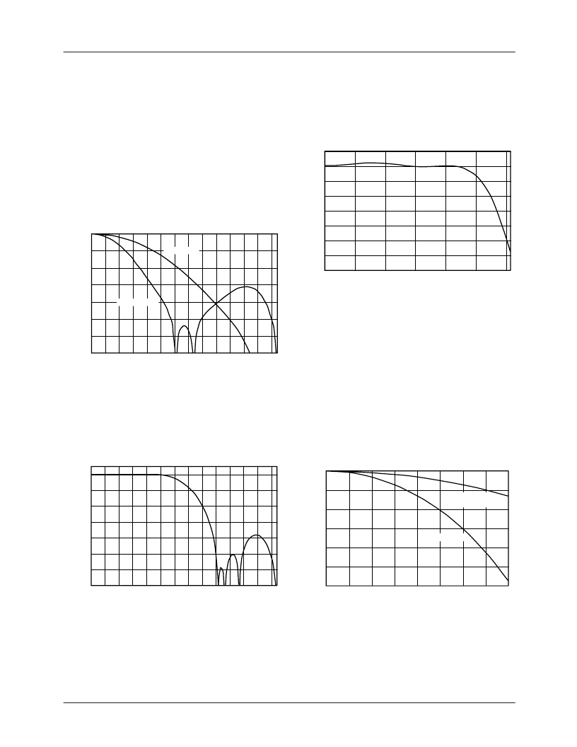
Filtering Within the TMC2490A
The TMC2490A incorporates internal digital filters to estab-
lish appropriate bandwidths and simplify external analog
reconstruction filter designs.
The chroma portion of the incoming digital video is band-
limited to reduce edge effect and other distortions of the
image compression process. Chrominance bandwidth is
selected by CHRBW. When LOW, the chrominance pass-
band attenuation is <3 dB within
±
650 kHz from f
SC
. The
stopband rejection is >26 dB outside f
SC
±
2 MHz. When
HIGH, the chrominance passband attenuation is <3 dB
within
±
1.3 MHz from f
SC
. The stopband rejection is
>33 dB outside f
SC
±
4 MHz.
Figure 9. Color-Difference Low-Pass Filter Response
The Chroma Modulator output and the luminance data are
digitally filtered with sharp-cutoff low-pass interpolation fil-
ters. These filters ensure that aliased subcarrier, chromi-
nance, and luminance frequencies are sufficiently suppressed
above the video base-band.
Figure 10. Chrominance and Luminance Interpolation
Filter
–
Full Spectrum Response
-70
-60
-50
-40
-30
-20
-10
0
0.0 0.5 1.0 1.5 2.0 2.5 3.0 3.5 4.0 4.5 5.0 5.5 6.0 6.5
Frequency (MHz)
A
24490A
Wideband
Narrowband
-70
-60
-50
-40
-30
-20
-10
0
0
1
2
3
4
5
6
7
8
9
10 11 12 13
Frequency (MHz)
A
24487A
Virtually all digital-to-analog converters have a response
with high frequency roll-off as a result of the zero-order hold
characteristic of classic D/A converters. This response is
commonly referred to as a sin(x)/x response. The sin(x)/x vs.
sampling frequency is shown in Figure 12.
Figure 11. Chrominance and Luminance Interpolation
Filter
–
Passband Detail
The TMC2490A’s digital interpolation filters convert the
data stream to a sample rate of twice the pixel rate. This
results in much less high frequency sin(x)/x rolloff and the
output spectrum between f
S
/4 and 3 x f
S
/4 contains very lit-
tle energy. Since there is so little signal energy in this fre-
quency band, the demands placed on the output
reconstruction filter are greatly reduced. The output filter
needs to be flat to f
S
/4 and have good rejection at 3 x f
S
/4.
The relaxed requirements greatly simplify the design of a fil-
ter with good phase response and low group delay distortion.
A small amount of peaking may be added to compensate
residual sin(x)/x rolloff.
Figure 12. Sin(x)/x Response
-3.5
-3.0
-2.5
-2.0
-1.5
-1.0
-0.5
0.0
0.5
0
1
2
Frequency (MHz)
3
4
5
6
A
24488A
-6
-5
-4
-3
-2
-1
0
0
1
2
3
4
5
6
7
8
Fs=13.5Msps
Fs=27.0Msps
(Oversampled)
Frequency (MHz)
A
24489A
相關(guān)PDF資料 |
PDF描述 |
|---|---|
| TMC2490AR2C | Multistandard Digital Video Encoder |
| TMC2490 | Digital Video Encoders(數(shù)字視頻編碼器) |
| TMC2491A | Multistandard Digital Video Encoder(多標(biāo)準(zhǔn)數(shù)字視頻編碼器) |
| TMCREOJ156KTR | Low ESR Tantalum Chip Capacitors |
| TMCR | Low ESR Tantalum Chip Capacitors |
相關(guān)代理商/技術(shù)參數(shù) |
參數(shù)描述 |
|---|---|
| TMC2490AR2C | 功能描述:視頻 IC Dig Video Decoder Multistandard RoHS:否 制造商:Fairchild Semiconductor 工作電源電壓:5 V 電源電流:80 mA 最大工作溫度:+ 85 C 封裝 / 箱體:TSSOP-28 封裝:Reel |
| TMC2490AR2CT | 功能描述:視頻 IC RoHS:否 制造商:Fairchild Semiconductor 工作電源電壓:5 V 電源電流:80 mA 最大工作溫度:+ 85 C 封裝 / 箱體:TSSOP-28 封裝:Reel |
| TMC249A | 制造商:未知廠家 制造商全稱:未知廠家 功能描述:High Current Microstep Stepper Motor Driver with sensorless stall detection, protection / diagnostics and SPI Interface |
| TMC249-A | 制造商:未知廠家 制造商全稱:未知廠家 功能描述:High Current Microstep Stepper Motor Driver with Sensorless Stall D e t e c t i o n ,P rotection / Diagnosis and SPI Interface |
| TMC249A-LA | 制造商:Trinamic 功能描述:IC BRIDGE DRIVER SPI/ANLG 32QFN |
發(fā)布緊急采購,3分鐘左右您將得到回復(fù)。