- 您現(xiàn)在的位置:買賣IC網(wǎng) > PDF目錄383990 > TDA9874AH (NXP SEMICONDUCTORS) Digital TV sound demodulator/decoder PDF資料下載
參數(shù)資料
| 型號: | TDA9874AH |
| 廠商: | NXP SEMICONDUCTORS |
| 元件分類: | 接收器 |
| 英文描述: | Digital TV sound demodulator/decoder |
| 中文描述: | AM/FM, AUDIO DEMODULATOR, PQFP44 |
| 封裝: | 14 X 14 MM, 2.20 MM HEIGHT, PLASTIC, SOT-205-1, QFP-44 |
| 文件頁數(shù): | 55/68頁 |
| 文件大小: | 231K |
| 代理商: | TDA9874AH |
第1頁第2頁第3頁第4頁第5頁第6頁第7頁第8頁第9頁第10頁第11頁第12頁第13頁第14頁第15頁第16頁第17頁第18頁第19頁第20頁第21頁第22頁第23頁第24頁第25頁第26頁第27頁第28頁第29頁第30頁第31頁第32頁第33頁第34頁第35頁第36頁第37頁第38頁第39頁第40頁第41頁第42頁第43頁第44頁第45頁第46頁第47頁第48頁第49頁第50頁第51頁第52頁第53頁第54頁當前第55頁第56頁第57頁第58頁第59頁第60頁第61頁第62頁第63頁第64頁第65頁第66頁第67頁第68頁
1999 Dec 03
55
Philips Semiconductors
Preliminary specification
Digital TV sound demodulator/decoder
TDA9874A
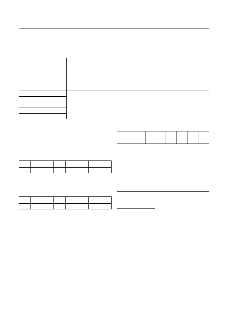
Table 83
Description of the DR2 bits
BIT
SYMBOL
DESCRIPTION
7
OVW
If this bit is HIGH, new additional data bits are written to the IC without the previous bits
being read.
When SAD = 1, new additional data is written into the IC. This bit is reset when the
additional data bits are read.
this bit is undefined
These 2 bits are CI bits decoded by majority logic from the parity checks of the last ten
samples in a frame.
6
SAD
5
4
3
2
1
0
CI1
CI2
AD10
AD9
AD8
the upper 3 bits of the additional data word
10.4.5
L
EVEL
R
EAD
-
OUT
R
EGISTERS
(LRRA
AND
LRRB)
These two bytes constitute a word that provides data from
a location that has been specified with the monitor select
register (see Section 10.3.4). The most significant byte of
the data is stored at subaddress 5.
Table 84
Level read-out register A (subaddress 5)
Note
1.
B7 is the most significant bit or sign bit of the word.
Table 85
Level read-out register B (subaddress 6)
Note
1.
B0 is the least significant bit of the word.
10.4.6
SIF L
EVEL
R
EGISTER
(SIFLR)
When the SIF AGC is on, bits B4 to B0 of this register
contain a number that gives an indication of the SIF input
level. That number can be interpreted in the same way as
the AGC gain register setting (see Section 10.3.2), i.e. if
the SIF AGCwere set to a fixed gain and the same number
loaded into the AGC gain register, the current SIF input
signal level would generate a SIF ADC output close to
full-scale.
When the SIF AGC is off, this register returns the contents
of the AGC gain register.
Bits B5 and B6 are don’t care.
Table 86
SIF level register (subaddress 7)
Table 87
Description of the SIF level bits
Note
1.
The pilot detector is faster than the stereo/dual
identification, but not as reliable and slightly less
sensitive. By means of the pilot detector bit, the control
software is able to identify an analog 2-carrier (A2)
standard transmission within approximately 0.1 s and
even in the event of a mono transmission (second
sound carrier with pilot). Certain NICAM test signals
may trigger a wrong pilot indication, therefore the pilot
detectorbitshouldnotbeevaluatedatchannel 2mixer
frequencies that correspond to NICAM carriers
(5.85 and 6.552 MHz). For detailed information,
please contact a Philips representative.
7
6
5
4
3
2
1
0
B7
(1)
B6
B5
B4
B3
B2
B1
B0
7
6
5
4
3
2
1
0
B7
B6
B5
B4
B3
B2
B1
B0
(1)
7
6
5
4
3
2
1
0
IDPILOT
B4
B3
B2
B1
B0
BIT
SYMBOL
DESCRIPTION
7
IDPILOT
IDPILOT bit:
when IDPILOT = 1
it indicates that an FM pilot
carrier in the 2nd channel is
detected; note 1
this bit is undefined
this bit is undefined
SIF level data bits:
these bits
correspond to the input level at
the selected SIF input
6
5
4
3
2
1
0
B4
B3
B2
B1
B0
相關(guān)PDF資料 |
PDF描述 |
|---|---|
| TDA9874APS | Digital TV sound demodulator/decoder |
| TDCS6440G | SONET/SDH 40 Gbits/s Cross Connect( SONET/SDH 40G位/秒交叉連接器件) |
| TDK5100F | 434 MHz ASK/FSK Transmitter in 10-pin Package |
| TDK5100 | ASK/FSK Transmitter 868/433 MHz |
| TE28F004S3-150 | BYTE-WIDE SMART 3 FlashFile MEMORY FAMILY 4, 8, AND 16 MBIT |
相關(guān)代理商/技術(shù)參數(shù) |
參數(shù)描述 |
|---|---|
| TDA9874AH/V2,557 | 功能描述:音頻放大器 DIGITAL STEREO DECODER VCR RoHS:否 制造商:STMicroelectronics 產(chǎn)品:General Purpose Audio Amplifiers 輸出類型:Digital 輸出功率: THD + 噪聲: 工作電源電壓:3.3 V 電源電流: 最大功率耗散: 最大工作溫度: 安裝風格:SMD/SMT 封裝 / 箱體:TQFP-64 封裝:Reel |
| TDA9874AHB | 功能描述:音頻放大器 DIGITAL STEREO DECODER VCR RoHS:否 制造商:STMicroelectronics 產(chǎn)品:General Purpose Audio Amplifiers 輸出類型:Digital 輸出功率: THD + 噪聲: 工作電源電壓:3.3 V 電源電流: 最大功率耗散: 最大工作溫度: 安裝風格:SMD/SMT 封裝 / 箱體:TQFP-64 封裝:Reel |
| TDA9874APS | 制造商:PHILIPS 制造商全稱:NXP Semiconductors 功能描述:Digital TV sound demodulator/decoder |
| TDA9874H | 制造商:PHILIPS 制造商全稱:NXP Semiconductors 功能描述:Digital TV sound demodulator/decoder |
| TDA9875 | 制造商:PHILIPS 制造商全稱:NXP Semiconductors 功能描述:Digital TV Sound Processor DTVSP |
發(fā)布緊急采購,3分鐘左右您將得到回復。