- 您現(xiàn)在的位置:買賣IC網(wǎng) > PDF目錄98181 > TC820CPL 1-CH DUAL-SLOPE ADC, PDIP40 PDF資料下載
參數(shù)資料
| 型號(hào): | TC820CPL |
| 元件分類: | ADC |
| 英文描述: | 1-CH DUAL-SLOPE ADC, PDIP40 |
| 封裝: | PLASTIC, DIP-40 |
| 文件頁數(shù): | 5/24頁 |
| 文件大小: | 185K |
| 代理商: | TC820CPL |
13
TC820
3-3/4 A/D Converter with Frequency
Counter and Logic Probe
TC820-10 10/17/96
2001 Microchip Technology Inc.
DS21476A
To prevent roll-over-type errors from being induced by
large common-mode voltages, CREF should be large com-
pared to stray node capacitance. A 0.1
F capacitor is
typical.
The TC820 offers a significantly improved analog
common temperature coefficient, providing a very stable
voltage suitable for use as a voltage reference. The
temperature coefficient of analog common is typically
35ppm/
°C.
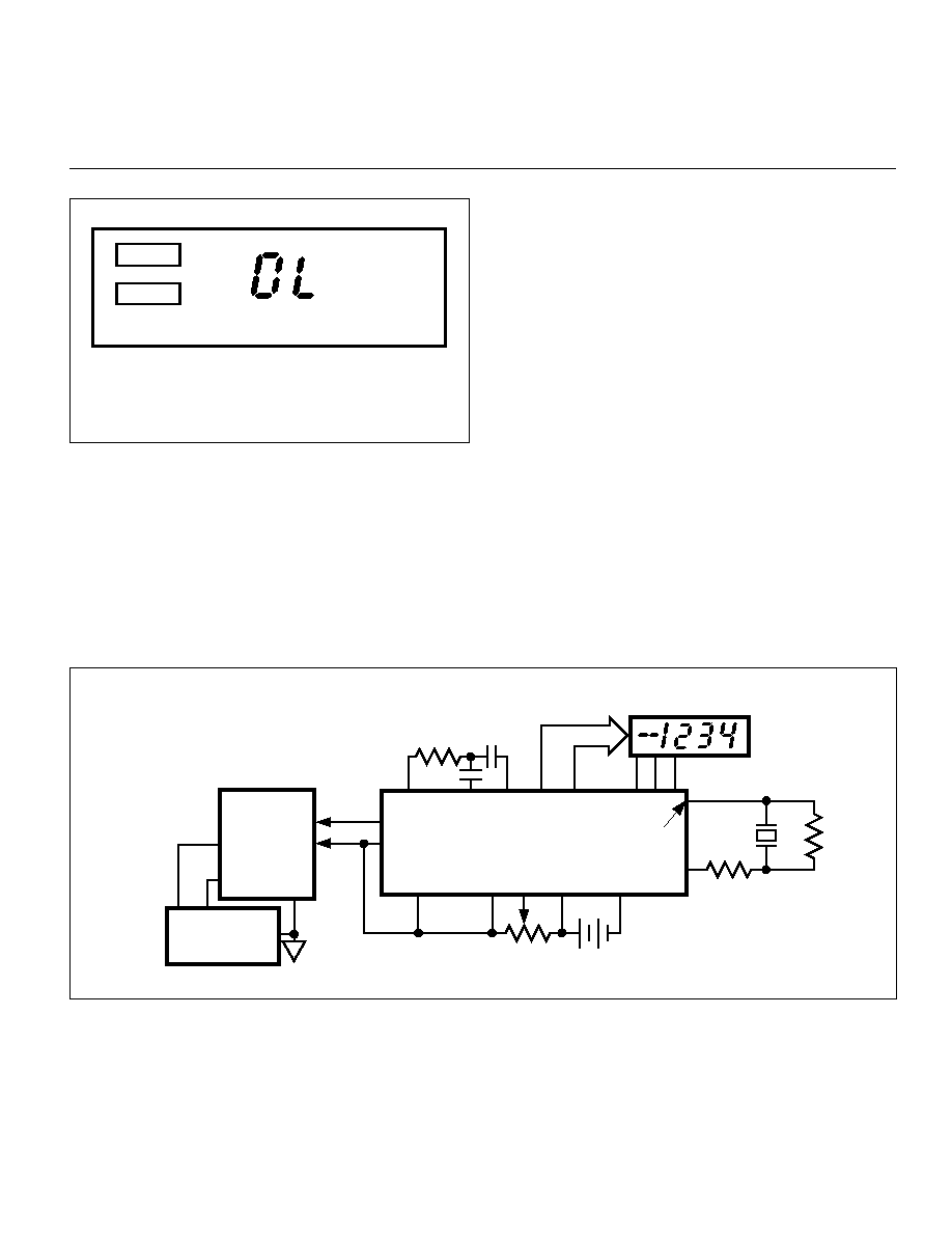
Figure 7. LCD During Logic Probe Operation
HIGH
LOW
*
**
"HIGH" ANNUNCIATOR WILL BE ON WHEN DP1/HI =
LOGIC HIGH
"LOW" ANNUNCIATOR AND BUZZER WILL BE ON
WHEN DP0/LO = LOGIC HIGH
**
*
Analog Common
The analog common pin is set at a voltage potential
approximately 3.3V below VDD. This potential is guaran-
teed to be between 3.15V and 3.45V below VDD. Analog
common is tied internally to an N-channel FET capable of
sinking 3mA. This FET will hold the common line at 3.3V
below VDD should an external load attempt to pull the
common line toward VDD. Analog common source current
is limited to 12
A, and is therefore easily pulled to a more
negative voltage (i.e., below VDD – 3.3V).
The TC820 connects the internal V+IN and V–IN inputs to
analog common during the auto-zero cycle. During the
reference integrate phase, V–IN is connected to analog
common. If V–IN is not externally connected to analog
common, a common-mode voltage exists. This is rejected
by the converter's 86dB common-mode rejection ratio. In
battery-powered applications, analog common and V–IN are
usually connected, removing common-mode voltage
concerns. In systems where V–IN is connected to the power
supply ground or to a given voltage, analog common should
be connected to V–IN.
The analog common pin serves to set the analog section
reference or common point. The TC820 is specifically
designed to operate from a battery or in any measurement
TC820
GND
V
+
V
–
V
+
V
–
MEASURED
SYSTEM
POWER
SOURCE
9V
VIN
VDD
VSS
V
+
REF
V
–
REF
+
VIN
–
VBUF
CAZ
BP1
INT
V
BP3
BP2
OSC1
OSC2
OSC3 NC
SEGMENT
DRIVE
LCD
ANALOG
COMMON
+
Figure 8. Common-Mode Voltage Removed in Battery Operation With V–IN = Analog Common
相關(guān)PDF資料 |
PDF描述 |
|---|---|
| TC820CLW | 1-CH DUAL-SLOPE ADC, PQCC44 |
| TC820CKW | 1-CH DUAL-SLOPE ADC, PQFP44 |
| TC823CKW | CONVERTER SUBSYSTEM ADC, PARALLEL ACCESS, PQFP44 |
| TC823EKW | CONVERTER SUBSYSTEM ADC, PARALLEL ACCESS, PQFP44 |
| TC823ELW | CONVERTER SUBSYSTEM ADC, PARALLEL ACCESS, PQCC44 |
相關(guān)代理商/技術(shù)參數(shù) |
參數(shù)描述 |
|---|---|
| TC8-20S2405R | 制造商:TRUMPOWER 制造商全稱:Tumbler Technologies + TRUMPower 功能描述:DC/DC CONVERTERS 2:1 Input, 12.5 to 20 Watt |
| TC8-20S4805R | 制造商:TRUMPOWER 制造商全稱:Tumbler Technologies + TRUMPower 功能描述:DC/DC CONVERTERS 2:1 Input, 12.5 to 20 Watt |
| TC-821-SC | 制造商:Thomas & Betts 功能描述:Cable Accessories Thin Wall Conduit Fitting Zinc Die Cast |
| TC821-SC-1 | 制造商:Thomas & Betts 功能描述:1/2 CONN,SSCREW,EMT,DC,INSUL,EA 制造商:Thomas & Betts 功能描述:ADVANTAGES OF STEEL CITY COMMERCIAL CONDUIT FITTINGS |
| TC821-SC-10 | 制造商:Thomas & Betts 功能描述:Fittings Connector 0.5inch Insulated |
發(fā)布緊急采購,3分鐘左右您將得到回復(fù)。