- 您現(xiàn)在的位置:買賣IC網(wǎng) > PDF目錄98151 > TA1275BFNG COLOR SIGNAL DECODER, PDSO24 PDF資料下載
參數(shù)資料
| 型號: | TA1275BFNG |
| 元件分類: | 顏色信號轉(zhuǎn)換 |
| 英文描述: | COLOR SIGNAL DECODER, PDSO24 |
| 封裝: | 0.300 INCH, 0.65 MM PITCH, PLASTIC, SSOP-24 |
| 文件頁數(shù): | 8/21頁 |
| 文件大小: | 1249K |
| 代理商: | TA1275BFNG |

TA1275BFNG
2005-03-14
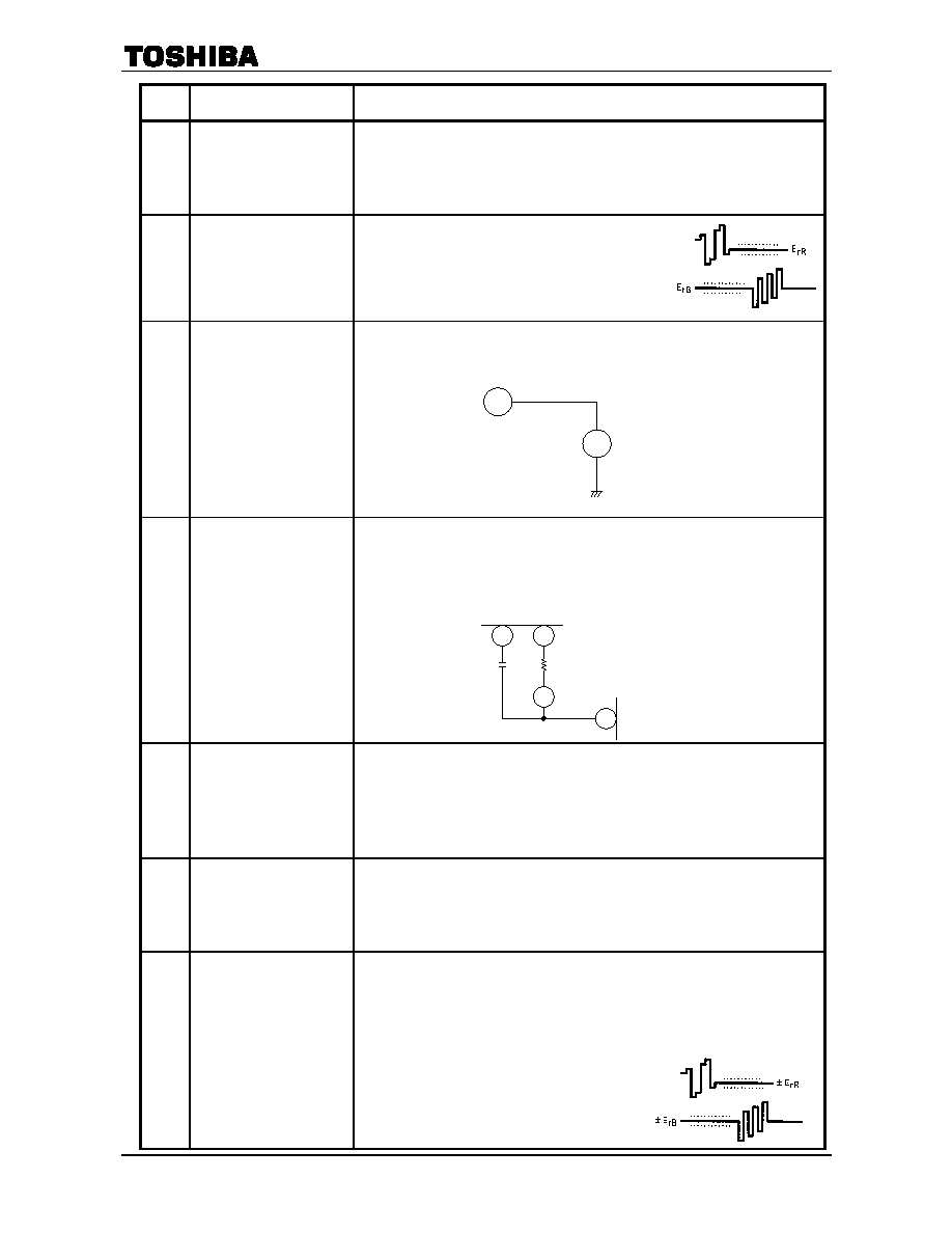
16
Note
Item
Test Condition
10
Killer ON/OFF Level
(1) : Input a 75% color bar (200 mVp-p at R ID) into Pin 20.
(2) : Decreasing the input amplitude, measure the amplitude at which
demodulated outputs disappear at Pin 9 and Pin 11, that is, "eSK".
(3) : Increasing the input amplitude from 0 mVp-p, measure the amplitude at which
demodulated outputs appear at Pin 9 and Pin 11, that is, "eSC".
11
Black Level Offset
(1) : Input a 200 mVp-p non-modulated chrome
signal into Pin 20.
(2) : Pin 10 and Pin 12 are opened.
(3) : Measure the difference between picture period and
blanking period at Pin 9 / Pin 11, that is, "ErR" /
"ErB".
12
ID Voltage
(1) : Connect the external power supply to Pin 13, as shown in the figure.
(2) : Apply 4.0 V to Pin 13, and measure the Pin 6 voltage, that is, “V6color”.
(3) : Apply 2.0 V to Pin 13, and measure the Pin 6 voltage, that is, “V6B / W”.
13
ID Current
(1) : Connect the external power supply to Pin 13, as shown in the figure.
(2) : Apply 5.0 V to Pin 13, and measure the Pin 6 current, that is, “I6strongSE”.
(3) : Apply 4.0 V to Pin 13, and measure the Pin 6 current, that is, “I6SE”.
(4) : Apply 2.0 V to Pin 13, and measure the Pin 6 current, that is, “I6B / W”.
14
System SW Threshold Level
(1) : Input a 200 mVp-p, 15 kHz sine wave into Pin 14 and Pin 16.
(2) : No input on Pin 20.
(3) : Increasing the Pin 6 voltage from 0 V, measure the voltage at which the 15 kHz
sine wave appears at Pin 9 and Pin 11, that is, "V6PIN".
(4) : Decreasing the Pin 6 voltage from 4 V, measure the voltage at which the 15 kHz
sine wave disappears at Pin 9 and Pin 11, that is, "V6S".
15
Color Difference Output DC
Level
(1) : No input on Pin 20.
(2) : Measure the DC voltage on Pin 9 / Pin 11 when Pin 6 is 4 V, that is, "V9PIN" /
"V11PIN".
(3) : Measure the DC voltage on Pin 9 / Pin 11 when Pin 6 is 0 V, that is, "V9S" /
"V11S".
16
R-Y B-Y Black Level Control
Characteristics
(1) : Input a 75% color bar (200 mVp-p at R ID) into Pin 20.
(2) : Measure the difference between the picture period and the blanking period at Pin
9 when Pin 10 is 5 V / 0 V, that is, ErR+ / ErR.
(3) : Measure the difference between the picture period and the blanking period at Pin
11 when Pin 12 is 5 V / 0 V, that is, ErB+ / ErB.
(4) : Calculate : "ErR+" = ErR+ErR
"ErR" = ErRErR
"ErB+" = ErB+ErB
"ErB" = ErBErB
6
V
-
+
Voltmeter
Ammeter
4
6
56
TA1275 BFNG
A
-
+
TB1309FG
15k
0.01F
相關(guān)PDF資料 |
PDF描述 |
|---|---|
| TA1275Z | SPECIALTY CONSUMER CIRCUIT, PZIP21 |
| TA1276AFG | SPECIALTY CONSUMER CIRCUIT, PQFP80 |
| TA1276AF | SPECIALTY CONSUMER CIRCUIT, PQFP80 |
| TA1281FA | 3-BAND, VIDEO TUNER, PDSO16 |
| TA1281F | 3-BAND, VIDEO TUNER, PDSO16 |
相關(guān)代理商/技術(shù)參數(shù) |
參數(shù)描述 |
|---|---|
| TA1275Z | 制造商:TOSHIBA 制造商全稱:Toshiba Semiconductor 功能描述:SECAM DEMODULATOR PROCESSOR |
| TA1276AFG | 制造商:TOSHIBA 制造商全稱:Toshiba Semiconductor 功能描述:PAL/NTSC Video Chroma And Deflection IC For CTV |
| TA1276AN | 制造商:Panasonic Industrial Company 功能描述:IC 制造商:Toshiba America Electronic Components 功能描述:Tv/Video Signal Proce or Toshiba IC 56-Pin DIP-S |
| TA1281 | 制造商:TOSHIBA 制造商全稱:Toshiba Semiconductor 功能描述:UHF/VHF TUNER IC |
| TA1281F | 制造商:TOSHIBA 制造商全稱:Toshiba Semiconductor 功能描述:UHF/VHF TUNER IC |
發(fā)布緊急采購,3分鐘左右您將得到回復(fù)。