- 您現(xiàn)在的位置:買賣IC網 > PDF目錄383876 > T8538A (Lineage Power) Quad Programmable Codec(四通道可編程編解碼器) PDF資料下載
參數(shù)資料
| 型號: | T8538A |
| 廠商: | Lineage Power |
| 元件分類: | Codec |
| 英文描述: | Quad Programmable Codec(四通道可編程編解碼器) |
| 中文描述: | 四可編程編解碼器(四通道可編程編解碼器) |
| 文件頁數(shù): | 23/42頁 |
| 文件大小: | 1019K |
| 代理商: | T8538A |
第1頁第2頁第3頁第4頁第5頁第6頁第7頁第8頁第9頁第10頁第11頁第12頁第13頁第14頁第15頁第16頁第17頁第18頁第19頁第20頁第21頁第22頁當前第23頁第24頁第25頁第26頁第27頁第28頁第29頁第30頁第31頁第32頁第33頁第34頁第35頁第36頁第37頁第38頁第39頁第40頁第41頁第42頁
Lucent Technologies Inc.
23
Advance Data Sheet
October 2000
T8538A Quad Programmable Codec
Electrical Characteristics
(continued)
Analog Interface
The following specifications pertain to the analog SLIC interface for each channel.
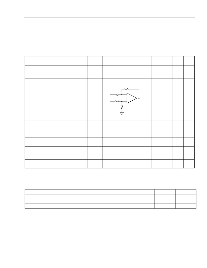
Table 7. Analog Interface
Table 8. Power Dissipation
Power measurements are made at BCLK = 2.048 MHz, DCLK = 2.048 MHz, no inputs from serial interface, inter-
face latches set as outputs, outputs unloaded.
Parameter
Symbol
R
VF
X
I
V
IX
Test Conditions
0.25 < V
IN
< (V
DDX
0.25) V
Relative to ground.
Signal should be capacitively
coupled to VF
X
I.
Min
100
1.4
Typ
—
1.5
Max
300
1.6
Unit
k
V
Input Resistance
dc Input Voltage
Load Resistance at VF
R
OP
and
VF
R
O
N
(differential)
R
L
5-8881F
7.5
—
—
k
Output Resistance
R
O
Digital input code correspond-
ing to idle PCM code (
μ
-law).
Digital input code correspond-
ing to idle PCM code (
μ
-law).
R
L
= 100 k
—
2
10
Output Offset Voltage Between VF
R
OP
and
VF
R
O
N
Output Offset Voltage Between
VF
R
OP
and
VF
R
O
N, Standby Mode
Common-mode Output Voltage, Active
Mode
V
OS
100
0
100
mV
V
OSS
20
0
20
mV
V
OCM
Digital input code correspond-
ing to alternating ± zero
μ
-law
PCM code.
—
1.4
1.5
1.6
V
Common-mode Output Voltage, Standby
Mode
V
OCMS
1.4
1.5
1.6
V
Parameter
Symbol
I
DDS
I
DD1
I
DD1
Test Conditions
—
—
—
Min
—
—
—
Typ
14
130
55
Max
—
—
—
Unit
mW
mW
mW
All Channels in Standby, Dissipation for One Channel
One Channel Active, Dissipation for Active Channel
Four Channels Active, Dissipation for One Channel
R
L
R
L
R
L
R
L
發(fā)布緊急采購,3分鐘左右您將得到回復。