- 您現(xiàn)在的位置:買賣IC網(wǎng) > PDF目錄374892 > SPLC782A (Electronic Theatre Controls, Inc.) 16COM/40SEG Controller/Driver PDF資料下載
參數(shù)資料
| 型號: | SPLC782A |
| 廠商: | Electronic Theatre Controls, Inc. |
| 英文描述: | 16COM/40SEG Controller/Driver |
| 中文描述: | 16COM/40SEG控制器/驅(qū)動器 |
| 文件頁數(shù): | 39/40頁 |
| 文件大小: | 1670K |
| 代理商: | SPLC782A |
第1頁第2頁第3頁第4頁第5頁第6頁第7頁第8頁第9頁第10頁第11頁第12頁第13頁第14頁第15頁第16頁第17頁第18頁第19頁第20頁第21頁第22頁第23頁第24頁第25頁第26頁第27頁第28頁第29頁第30頁第31頁第32頁第33頁第34頁第35頁第36頁第37頁第38頁當(dāng)前第39頁第40頁
SPLC782A
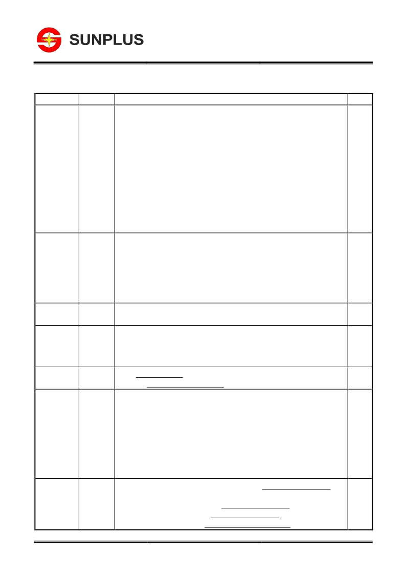
11. REVISION HISTORY
Sunplus Technology Co., Ltd.
Proprietary & Confidential
39
FEB. 15, 2005
Version: 1.7
Date
Revision #
Description
Page
FEB. 15, 2005
1.7
1. Modify from TYPE to DIRC in section 5.20 Common data Direction
2. Add description(T
A
=25
℃
) in section 6.5.1 and 6.5.2
3. Correct the description of Figure 5-4
4. Correct the code of 5.2.9 Read busy flag and address
SunpusConidenia
5. Modify the execution time of 5.3 Instruction table
Fo PARTMNERUseOny
6. Remove the note of Figure 5-16
7. Correct the display of 14~21 of Figure 5-17
8. Insert the display of 10 of Figure 5-19
9. Modify the Driver Supply voltage of 6.1 absolute maximum ratings
10. Modify the operation current of IDD1 and IDD2 of 6.2 DC Characteristics and 6.3 DC
Characteristics
11. Add the operation current of Ipp of of 6.2 DC Characteristics and 6.3 DC Characteristics
12. Add the description of max. and min. of Fosc of Figure 6-3
22
26
6
7
8
8
9
10
24
24-25
24-25
27
DEC. 24, 2004
1.6
1. Add figure number for all figure
2. Modify 6.2 IIL max. Value to -100uA
3. Modify 6.3 IIL max. Value to -150uA
4. Modify 6.3 VIH1 min. Value to 0.7VDD
5. Modify TA of all DC/AC Characteristics to TA=-20
℃
to +75
℃
6. Modify 6.5.3 and 6.5.4 E Cycle time to 1250ns
7. Modify 6.5.3 and 6.5.4 E Pulse Width to 600ns
24
24
24
24 - 26
26
26
APR. 23, 2004
1.5
1. Modify description:
“Execution time”
to
“Execution time (Temp = 25
℃
)”
2. Modify Note2: from 2.3ms to 4.1ms
8
8
APR. 01, 2004
1.4
1. Add min. and max. value in Instruction Table
2. Add 8-bit/4-bit data transfer timing sequence example
3. Add
“
6.8
The Following Graps Show the Relationship Between FOSC and Temperature”
4. Add Note2 in Instruction Table
8
18 - 19
27
8
JUN. 20, 2003
1.3
1. Add
“
8.3 SPLC782A - 22
”
2. Remove
“
9. PACKAGE/PAD LOCATIONS
”
33
34
MAY. 09, 2002
1.2
1. Correct PIN No. error
V2 pin: 21 to 22
V3 pin: 22 to 21
R/W pin: 25 to 26
RS pin: 26 to 25
MOD1 pin: 17 to 18
MOD0 pin: 18 to 17
2. Correct ROM size: 160 5*8 dot -> 192 5*8 dot character patterns
32 5*10 dot -> 64 5*10 dot character patterns
5
13
NOV. 26, 2001
1.1
1. Modify
“
MODE1
“
to
“
MOD1
“
,
“
MODE2
“
to
“
MOD0
“
in the
“
4. SIGNAL DESCRIPTIONS
”
2. Modify pins
“
CL2
”
and
“
D
“
description:
“
normal mode
”
to
“
normally use
”
in the
“
4. SIGNAL DESCRIPTIONS
”
3. Modify pin OSC1 description in the
“
4. SIGNAL DESCRIPTIONS
”
4. Modify DC Characteristics in the
“
6. ELECTRICAL SPECIFICATIONS
”
5
5
5
21
相關(guān)PDF資料 |
PDF描述 |
|---|---|
| SPLC783A | 16COM/80SEG Controller/Driver |
| SPLCG81 | Laser Diode on Submount 1.0 W cw Class 4 Laser Product |
| SPLCG85 | Laser Diode on Submount 1.0 W cw Class 4 Laser Product |
| SPLCG94 | Laser Diode on Submount 1.0 W cw Class 4 Laser Product |
| SPLCG98 | Laser Diode on Submount 1.0 W cw Class 4 Laser Product |
相關(guān)代理商/技術(shù)參數(shù) |
參數(shù)描述 |
|---|---|
| SPLC783A | 制造商:未知廠家 制造商全稱:未知廠家 功能描述:16COM/80SEG Controller/Driver |
| SPLCG65 | 制造商:OSRAM 制造商全稱:OSRAM 功能描述:Rote Laser Diode in offener Bauform 0.5 W cw |
| SPLCG81 | 制造商:INFINEON 制造商全稱:Infineon Technologies AG 功能描述:Laser Diode on Submount 1.0 W cw Class 4 Laser Product |
| SPLCG81-2S | 制造商:OSRAM 功能描述:Laser diode, C-mount,2W,808nm |
| SPLCG85 | 制造商:INFINEON 制造商全稱:Infineon Technologies AG 功能描述:Laser Diode on Submount 1.0 W cw Class 4 Laser Product |
發(fā)布緊急采購,3分鐘左右您將得到回復(fù)。