- 您現(xiàn)在的位置:買賣IC網(wǎng) > PDF目錄98141 > SPC5668GF0AVMG (FREESCALE SEMICONDUCTOR INC) 32-BIT, FLASH, 116 MHz, MICROCONTROLLER, PBGA208 PDF資料下載
參數(shù)資料
| 型號: | SPC5668GF0AVMG |
| 廠商: | FREESCALE SEMICONDUCTOR INC |
| 元件分類: | 微控制器/微處理器 |
| 英文描述: | 32-BIT, FLASH, 116 MHz, MICROCONTROLLER, PBGA208 |
| 封裝: | 17 X 17 MM, 1 MM PITCH, ROHS COMPLIANT, MO151AAF-1, MAPBGA-208 |
| 文件頁數(shù): | 26/66頁 |
| 文件大小: | 593K |
| 代理商: | SPC5668GF0AVMG |
第1頁第2頁第3頁第4頁第5頁第6頁第7頁第8頁第9頁第10頁第11頁第12頁第13頁第14頁第15頁第16頁第17頁第18頁第19頁第20頁第21頁第22頁第23頁第24頁第25頁當(dāng)前第26頁第27頁第28頁第29頁第30頁第31頁第32頁第33頁第34頁第35頁第36頁第37頁第38頁第39頁第40頁第41頁第42頁第43頁第44頁第45頁第46頁第47頁第48頁第49頁第50頁第51頁第52頁第53頁第54頁第55頁第56頁第57頁第58頁第59頁第60頁第61頁第62頁第63頁第64頁第65頁第66頁
MPC5668x Microcontroller Data Sheet, Rev. 5
Electrical Characteristics
Freescale Semiconductor
32
4.6
Operating Current Specifications
2 Voltage overshoots during a high-to-low or low-to-high transition must not exceed 10 seconds per instance.
3 5.3 V for 10 hours cumulative time, 3.3 V +10% for time remaining.
4 6.4 V for 10 hours cumulative time, 5.0 V +10% for time remaining.
5 V
DDE1 – VDDE4 are separate power segments and may be powered independently with no differential voltage constraints
between the power segments. VDDE1 – VDDE3 pad power segments contain ADC analog input channels and thus the input
analog signal level may be clamped to the VDDE level, resulting in inaccurate ADC results if the VDDE voltage level is less than
VDDA.
6 When V
RCSEL = VDDA (high), the internally generated VDD33 voltage may be used to power VDDEMLB as long as the PK[0:2]
pads remain in the disabled default state with their output buffers, input buffers, and pull devices disabled.
7 The pad type is indicated by one or more of the following abbreviations: A–analog, F—fast speed, H–high voltage, I—input-only,
M–medium speed, S–slow speed. For example, pad type SH designates a slow high-voltage pad.
8 The IHA pads are related to V
DDA.
9 Characterization Based Capability:
IOH_F = {12, 20, 30, 40} mA and IOL_F = {24, 40, 50, 65} mA for {00, 01,10, 11} drive mode with VDDE = 3.0 V;
IOH_F = {7, 13, 18, 25} mA and IOL_F = {18, 30, 35, 50} mA for {00, 01, 10, 11} drive mode with VDDE =2.25 V;
IOH_F = {3, 7, 10, 15} mA and IOL_F = {12, 20, 27, 35} mA for {00, 01, 10, 11} drive mode with VDDE =1.62 V.
10 Characterization Based Capability:
IOH_S = {6, 11.6} mA and IOL_S = {9.2, 17.7} mA for {slow, medium} I/O with VDDEH = 4.5 V;
IOH_S = {2.8, 5.4} mA and IOL_S = {4.2, 8.1} mA for {slow, medium} I/O with VDDEH = 3.0 V
11 All V
OL/VOH values 100% tested with ±2 mA load.
12 Absolute value of current, measured at V
IL and VIH.
13 Weak pull up/down inactive. Measured at V
DDE = 5.25 V. Applies to pad types: SH and MH. Leakage specification guaranteed
only when power supplies are within specified operating conditions.
14 Maximum leakage occurs at maximum operating temperature. Leakage current decreases by approximately one-half for each
8 to 12 oC, in the ambient temperature range of 50 to 125 oC. Applies to pad types: pad_a and pad_ae.
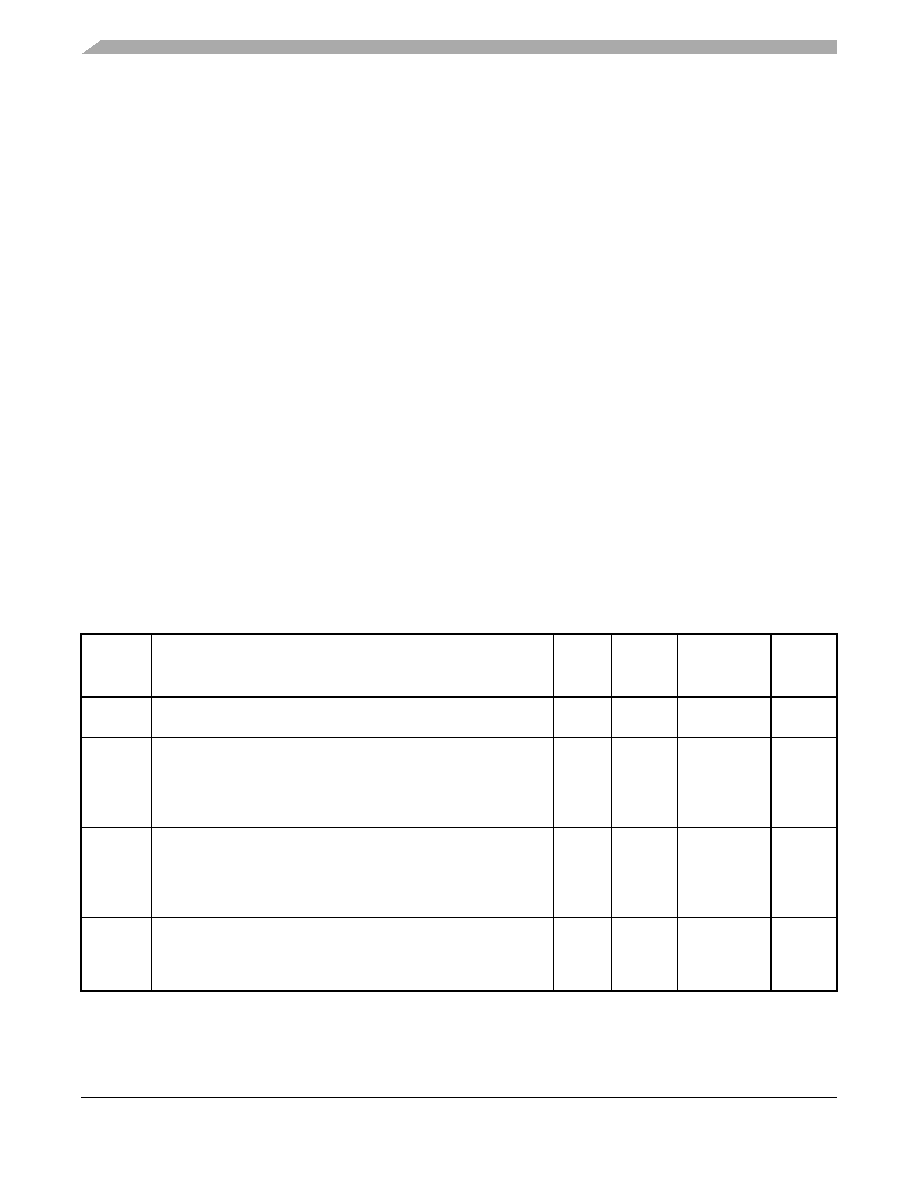
Table 9. Operating Currents
Spec
Characteristic
Symbol
Typ1
25
C
Ambient
Max1
–40–150
C
Junction
Unit
Equations ITOTAL =IDDE +IDDA +IRH +IDD33 +IDDSYN +IRC +IDD
IDDE =IDDE1 +IDDE2 +IDDE3 +IDDE4 +IDDEMLB
—
1VDDE Current
VDDE(1,2,3,4) @ 3.0V–5.5 V
VDDEMLB @ 2.375V–3.6 V
Static2
Dynamic3
IDDE
0
Note 3
30
25
A
mA
2VDDA Current
VDDA @ 3.0V–5.5 V
Run mode
Sleep mode
– Optional 32 kHz osc enabled
IDDA
1
20
+5
30
50
+15
mA
A
3VRH Current
VRH @ 3.0V–5.5 V
Run mode
Sleep mode
IRH
300
1
700
30
A
相關(guān)PDF資料 |
PDF描述 |
|---|---|
| SPC5668GF0AVMJ | 32-BIT, FLASH, 116 MHz, MICROCONTROLLER, PBGA256 |
| SPD6729QCE | PCMCIA BUS CONTROLLER, PQFP208 |
| SPEAR-09-B042 | 1 CHANNEL(S), 100M bps, I2C BUS CONTROLLER, PBGA289 |
| SPEAR300-2 | 32-BIT, FLASH, 333 MHz, RISC MICROCONTROLLER, PBGA289 |
| SPL505YC264ATT | PROC SPECIFIC CLOCK GENERATOR, PDSO64 |
相關(guān)代理商/技術(shù)參數(shù) |
參數(shù)描述 |
|---|---|
| SPC5668GF0AVMGR | 制造商:FREESCALE 制造商全稱:Freescale Semiconductor, Inc 功能描述:MPC5668x Microcontroller Data Sheet |
| SPC5668GF0AVMJ | 制造商:FREESCALE 制造商全稱:Freescale Semiconductor, Inc 功能描述:MPC5668x Microcontroller Data Sheet |
| SPC5668GF0AVMJR | 制造商:FREESCALE 制造商全稱:Freescale Semiconductor, Inc 功能描述:MPC5668x Microcontroller Data Sheet |
| SPC5668GF1AMMG | 功能描述:32位微控制器 - MCU 32B,2M NVM, GATEWAY RoHS:否 制造商:Texas Instruments 核心:C28x 處理器系列:TMS320F28x 數(shù)據(jù)總線寬度:32 bit 最大時鐘頻率:90 MHz 程序存儲器大小:64 KB 數(shù)據(jù) RAM 大小:26 KB 片上 ADC:Yes 工作電源電壓:2.97 V to 3.63 V 工作溫度范圍:- 40 C to + 105 C 封裝 / 箱體:LQFP-80 安裝風(fēng)格:SMD/SMT |
| SPC5668GF1AMMGR | 制造商:FREESCALE 制造商全稱:Freescale Semiconductor, Inc 功能描述:MPC5668x Microcontroller Data Sheet |
發(fā)布緊急采購,3分鐘左右您將得到回復(fù)。