- 您現(xiàn)在的位置:買賣IC網(wǎng) > PDF目錄98027 > SPC5121YVY400BR (FREESCALE SEMICONDUCTOR INC) RISC PROCESSOR, PBGA516 PDF資料下載
參數(shù)資料
| 型號: | SPC5121YVY400BR |
| 廠商: | FREESCALE SEMICONDUCTOR INC |
| 元件分類: | 微控制器/微處理器 |
| 英文描述: | RISC PROCESSOR, PBGA516 |
| 封裝: | 27 X 27 MM, 2.25 MM HEIGHT, 1 MM PITCH, ROHS COMPLIANT, PLASTIC, TFBGA-516 |
| 文件頁數(shù): | 61/86頁 |
| 文件大小: | 719K |
| 代理商: | SPC5121YVY400BR |
第1頁第2頁第3頁第4頁第5頁第6頁第7頁第8頁第9頁第10頁第11頁第12頁第13頁第14頁第15頁第16頁第17頁第18頁第19頁第20頁第21頁第22頁第23頁第24頁第25頁第26頁第27頁第28頁第29頁第30頁第31頁第32頁第33頁第34頁第35頁第36頁第37頁第38頁第39頁第40頁第41頁第42頁第43頁第44頁第45頁第46頁第47頁第48頁第49頁第50頁第51頁第52頁第53頁第54頁第55頁第56頁第57頁第58頁第59頁第60頁當(dāng)前第61頁第62頁第63頁第64頁第65頁第66頁第67頁第68頁第69頁第70頁第71頁第72頁第73頁第74頁第75頁第76頁第77頁第78頁第79頁第80頁第81頁第82頁第83頁第84頁第85頁第86頁
MPC5121E/MPC5123 Data Sheet, Rev. 3
Electrical and Thermal Characteristics
Freescale Semiconductor
64
3.3.16
SPDIF
The Sony/Philips Digital Interface (SPDIF) timing is totally asynchronous, therefore there is no need for relationship with the
clock.
3.3.17
CAN
The CAN functions are available as TX and CAN3/4_RX pins at normal IO pads and as CAN1/2 RX pins at the VBAT_RTC
domain. There is no filter for the WakeUp dominant pulse. Any High-to-Low edge can cause WakeUp, if configured.
3.3.18
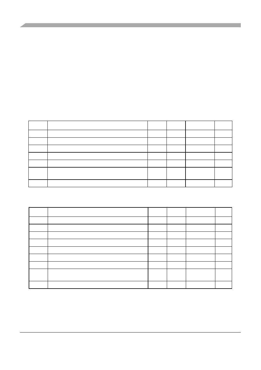
I2C
This section specifies the timing parameters of the Inter-Integrated Circuit (I2C) interface. Refere to the I2C-Bus Specification.
Table 39. I2C Input Timing Specifications – SCL and SDA
Sym
Description
Min
Max
Units
SpecID
1
Start condition hold time
2
—
IP-Bus Cycle1
1 Inter Peripheral Clock is defined in the MPC5121e/MPC5123 Reference Manual.
A18.1
2
Clock low time
8
—
IP-Bus Cycle1
A18.2
4
Data hold time
0.0
—
ns
A18.3
6
Clock high time
4
—
IP-Bus Cycle1
A18.4
7
Data setup time
0.0
—
ns
A18.5
8
Start condition setup time (for repeated start condition
only)
2
—
IP-Bus Cycle1
A18.6
9
Stop condition setup time
2
—
IP-Bus Cycle1
A18.7
Table 40. I2C Output Timing Specifications – SCL and SDA
Sym
Description
Min
Max
Units
SpecID
11
1 Programming IFDR with the maximum frequency results in the minimum output timings listed. The I2C interface is
designed to scale the data transition time, moving it to the middle of the SCL low period. The actual position is
affected by the prescale and division values programmed in IFDR.
Start condition hold time
6
—
IP-Bus Cycle2
2 Because SCL and SDA are open-drain-type outputs, which the processor can only actively drive low, the time SCL
or SDA takes to reach a high level depends on external signal capacitance and pull-up resistor values
A18.8
21
Clock low time
10
—
IP-Bus Cycle2
A18.9
33
SCL/SDA rise time
—
7.9
ns
A18.10
Data hold time
7
—
IP-Bus Cycle2
A18.11
SCL/SDA fall time
—
7.9
ns
A18.12
Clock high time
10
—
IP-Bus Cycle2
A18.13
Data setup time
2
—
IP-Bus Cycle2
A18.14
Start condition setup time (for repeated start condition
only)
20
—
IP-Bus Cycle2
A18.15
Stop condition setup time
10
—
IP-Bus Cycle2
A18.16
相關(guān)PDF資料 |
PDF描述 |
|---|---|
| MPC601CQ50A | RISC PROCESSOR |
| MPC601CQ66A | 32-BIT, 66 MHz, RISC PROCESSOR, CQFP304 |
| MPC604ERX300XX | RISC PROCESSOR, CBGA255 |
| MPC7410RX550PE | 32-BIT, 550 MHz, RISC PROCESSOR, CBGA360 |
| MPC7410RX450PER2 | 32-BIT, 450 MHz, RISC PROCESSOR, CBGA360 |
相關(guān)代理商/技術(shù)參數(shù) |
參數(shù)描述 |
|---|---|
| SPC5123YVY300B | 制造商:FREESCALE 制造商全稱:Freescale Semiconductor, Inc 功能描述:Advance Information |
| SPC5123YVY300BR | 制造商:FREESCALE 制造商全稱:Freescale Semiconductor, Inc 功能描述:Advance Information |
| SPC5123YVY400B | 制造商:FREESCALE 制造商全稱:Freescale Semiconductor, Inc 功能描述:e300 Power Architecture processor core |
| SPC5123YVY400BR | 制造商:FREESCALE 制造商全稱:Freescale Semiconductor, Inc 功能描述:e300 Power Architecture processor core |
| SPC5125 | 制造商:ELECTROMAGNETIC CORPORATI 功能描述:_ |
發(fā)布緊急采購,3分鐘左右您將得到回復(fù)。