- 您現(xiàn)在的位置:買賣IC網(wǎng) > PDF目錄1969 > SP506CM-L (Exar Corporation)IC TXRX WAN MULTI-MODE 80LQFP PDF資料下載
參數(shù)資料
| 型號(hào): | SP506CM-L |
| 廠商: | Exar Corporation |
| 文件頁(yè)數(shù): | 8/35頁(yè) |
| 文件大?。?/td> | 0K |
| 描述: | IC TXRX WAN MULTI-MODE 80LQFP |
| 標(biāo)準(zhǔn)包裝: | 84 |
| 類型: | 收發(fā)器 |
| 驅(qū)動(dòng)器/接收器數(shù): | 7/7 |
| 規(guī)程: | 多協(xié)議 |
| 電源電壓: | 5V |
| 安裝類型: | 表面貼裝 |
| 封裝/外殼: | 80-LQFP |
| 供應(yīng)商設(shè)備封裝: | 80-LQFP(14x14) |
| 包裝: | 托盤 |
| 其它名稱: | 1016-1441 SP506CM-L-ND |
第1頁(yè)第2頁(yè)第3頁(yè)第4頁(yè)第5頁(yè)第6頁(yè)第7頁(yè)當(dāng)前第8頁(yè)第9頁(yè)第10頁(yè)第11頁(yè)第12頁(yè)第13頁(yè)第14頁(yè)第15頁(yè)第16頁(yè)第17頁(yè)第18頁(yè)第19頁(yè)第20頁(yè)第21頁(yè)第22頁(yè)第23頁(yè)第24頁(yè)第25頁(yè)第26頁(yè)第27頁(yè)第28頁(yè)第29頁(yè)第30頁(yè)第31頁(yè)第32頁(yè)第33頁(yè)第34頁(yè)第35頁(yè)

6
Exar Coporation 48720 Kato Road, Fremont CA, 94538 (50) 668-7000 Fax (50) 668-707 www.exar.com
SP506_0_0870
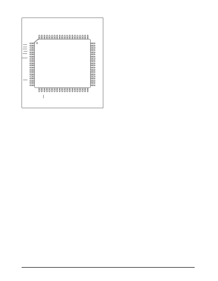
PINOUT…
PIN ASSIGNMENTS…
CLOCK AND DATA GROUP
Pin — RxD — Receive Data; TTL output,
sourced from RD(a) and RD(b) inputs.
Pin 4 — TxD — TTL input ; transmit data
source for SD(a) and SD(b) outputs.
Pin 5 — TxC — Transmit Clock; TTL input
for TT driver outputs.
Pin 20 — RxC — Receive Clock;TTLoutput
sourced from RT(a) and RT(b) inputs.
Pin 22 — ST — Send Timing; TTL input;
source for ST(a) and ST(b) outputs.
Pin 37 — RT(a) — Receive Timing; analog
input, inverted; source for RxC.
Pin 38 — RT(b) — Receive Timing; analog
input, non-inverted; source for RxC.
Pin 42 — ST(a) — Send Timing; analog
output, inverted; sourced from ST.
Pin 44 — ST(b) — Send Timing; analog
output, non-inverted; sourced from ST.
Pin 59 — SD(b) —Analog Out — Send data,
non-inverted; sourced from TxD.
Pin 6 — SD(a) — Analog Out — Send
data, inverted; sourced from TxD.
Pin 63 — TT(a) — Analog Out — Terminal
Timing, inverted; sourced from TxC
Pin 65 — TT(b) — Analog Out — Terminal
Timing, non–inverted; sourced from TxC.
Pin 70 — RD(a) — Receive Data, analog
input; inverted; source for RxD.
Pin 7 — RD(b) — Receive Data; analog
input; non-inverted; source for RxD.
Pin 76 — SCT(a) — Serial Clock Transmit;
analog input, inverted; source for SCT.
Pin 77 — SCT(b) — Serial Clock Transmit:
analog input, non–inverted; source for
SCT
Pin 79 — SCT — Serial Clock Transmit; TTL
output; sources from SCT(a) and SCT(b)
inputs.
CONTROL LINE GROUP
Pin 3 — DTR — Data Terminal Ready; TTL
input; source for TR(a) and TR(b) outputs.
Pin 6 — RTS — Ready To Send; TTL input;
source for RS(a) and RS(b) outputs.
Pin7—RL—RemoteLoopback;TTLinput;
source for RL(a) and RL(b) outputs.
Pin 9 — DCD— Data Carrier Detect; TTL
output; sourced from RR(a) and RR(b)
inputs.
Pin 2 — RI — Ring In; TTL output; sourced
from IC(a) and IC(b) inputs.
Pin 24 — LL — Local Loopback; TTL input;
source for LL(a) and LL(b) outputs.
Pin 35 — RR(a)— Receiver Ready; analog
input, inverted; source for DCD.
Pin 36 — RR(b)— Receiver Ready; analog
input, non-inverted; source for DCD.
Pin 39 — IC(a)— Incoming Call; analog
input, inverted; source for RI.
Pin 40 — IC(b)— Incoming Call; analog
input,non-inverted; source for RI.
RxD 1
SDEN 2
TREN3
RSEN4
LLEN 5
TTEN 6
SCTEN7
LATCH 8
DEC
3
9
DEC
2 10
DEC
1 11
DEC
0 12
DTR 13
TxD 14
TxC 15
RTS 16
RL 17
RLEN 18
DCD 19
RxC 20
RI
21
ST
22
STEN
23
LL
24
V CC
25
C 1
+
26
V DD
27
C 2
+
28
GND
29
C 1
–
30
C 2
–
31
V SS
32
V CC
33
GND
34
RR(a)
35
RR(b)
36
RT(a)
37
RT(b)
38
IC(a)
39
IC(b)
40
60 GND
59 SD(b)
58 TR(a)
57 GND
56 TR(b)
55 VCC
54 RS(a)
53 GND
52 RS(b)
51 LL(a)
50 GND
49 LL(b)
48 VCC
47 RL(a)
46 GND
45 RL(b)
44 ST(b)
43 GND
42 ST(a)
41 VCC
80
CTS
79
SCT
78
DSR
77
SCT(b)
76
SCT(a)
75
GND
74
V CC
73
V CC
72
GND
71
RD(b)
70
RD(a)
69
DM(b)
68
DM(a)
67
CS(b)
66
CS(a)
65
TT(b)
64
GND
63
TT(a)
62
V CC
61
SD(a)
SP506
相關(guān)PDF資料 |
PDF描述 |
|---|---|
| SP507CM-L | IC TXRX WAN MULTI-MODE 80LQFP |
| SP508EF-L | IC TXRX MULTIPROTOCOL 100LQFP |
| SP510CM-L | IC TXRX MULTIPROTOCOL HS 100LQFP |
| SP526CF-L | IC TXRX WAN MULTI-MODE 44LQFP |
| SP5301CY-L/TR | IC TXRX SERIAL BUS UNIV 14TSSOP |
相關(guān)代理商/技術(shù)參數(shù) |
參數(shù)描述 |
|---|---|
| SP506CM-L | 制造商:Exar Corporation 功能描述:IC WAN MULTIMODE SER TXRX 5.25V LQFP80 |
| SP506EB | 制造商:SIPEX 制造商全稱:Sipex Corporation 功能描述:Multi-Protocol Serial Transceivers |
| SP506EK | 制造商:SIPEX 制造商全稱:Sipex Corporation 功能描述:Multi-Protocol Serial Transceivers |
| SP506RB | 制造商:SIPEX 制造商全稱:Sipex Corporation 功能描述:Multi-Protocol Serial Transceivers |
| SP507 | 制造商:SIPEX 制造商全稱:Sipex Corporation 功能描述:+5V, Single Chip WAN Multi-Mode Serial Transceiver |
發(fā)布緊急采購(gòu),3分鐘左右您將得到回復(fù)。