- 您現(xiàn)在的位置:買賣IC網(wǎng) > PDF目錄1969 > SP506CM-L (Exar Corporation)IC TXRX WAN MULTI-MODE 80LQFP PDF資料下載
參數(shù)資料
| 型號: | SP506CM-L |
| 廠商: | Exar Corporation |
| 文件頁數(shù): | 14/35頁 |
| 文件大小: | 0K |
| 描述: | IC TXRX WAN MULTI-MODE 80LQFP |
| 標(biāo)準(zhǔn)包裝: | 84 |
| 類型: | 收發(fā)器 |
| 驅(qū)動(dòng)器/接收器數(shù): | 7/7 |
| 規(guī)程: | 多協(xié)議 |
| 電源電壓: | 5V |
| 安裝類型: | 表面貼裝 |
| 封裝/外殼: | 80-LQFP |
| 供應(yīng)商設(shè)備封裝: | 80-LQFP(14x14) |
| 包裝: | 托盤 |
| 其它名稱: | 1016-1441 SP506CM-L-ND |
第1頁第2頁第3頁第4頁第5頁第6頁第7頁第8頁第9頁第10頁第11頁第12頁第13頁當(dāng)前第14頁第15頁第16頁第17頁第18頁第19頁第20頁第21頁第22頁第23頁第24頁第25頁第26頁第27頁第28頁第29頁第30頁第31頁第32頁第33頁第34頁第35頁
2
Exar Coporation 48720 Kato Road, Fremont CA, 94538 (50) 668-7000 Fax (50) 668-707 www.exar.com
SP506_0_0870
mode selection is done via a 4–bit control
word, which is the same as the driver's 4-bit
control word.
Like the drivers, the receivers are prear-
ranged for the specific requirements of
the synchronous serial interface. As the
operating mode of the receivers is changed,
the electrical characteristics will change to
support the requirements of clock, data,
and control line receivers. Table 2 shows
the mode of each receiver in the different
interface modes that can be selected.
There are three basic types of receiver cir-
cuits — V.28, V.0, and V..
V.28 Receivers
The V.28 receiver is single–ended and ac-
cepts V.28 signals from the V.28 driver. The
V.28receiverhasanoperatingvoltagerange
of+5Vandcanreceivesignalsdownto +3V.
The input sensitivity complies with RS-232
and V.28 specifications at +3V. The input
impedance is 3k to 7k in accordance to
RS-232 and V.28 over a +5V input range.
The receiver output produces a TTL/CMOS
signal with a +2.4V minimum for a logic ""
and a +0.8V maximum for a logic "0". V.28
receivers are used in RS-232 mode for all
data,clockandcontrolsignals. Theyarealso
used in V.35 mode for control line signals:
CTS, DSR, LL, and RL. The V.28 receivers
can operate to at least 20kbps.
V.10 Receivers
The V.0 receivers are also single–ended
as with the V.28 receivers but have an in-
put threshold as low as +200mV. The input
impedance is guaranteed to be greater than
4K, with an operating voltage range of +7V.
The V.0 receivers can operate to at least
20kbps. V.0 receivers are used in RS-
449, EIA-530, EIA-530A and V.36 modes
as Category II signals as indicated by their
corresponding specifications.
V.11 Receivers
The third type of receiver is a differential
which supports V. and RS-485 signals.
This receiver has a typical input impedance
of 0k and a typical differential threshold
of +200mV, which complies with the V.
specification.Sincethecharacteristicsofthe
V. receivers are actually subsets of RS-
485, the V. receivers can accept RS-485
signals. However, these receivers cannot
support32-transceiversonthesignalbusdue
to the lower input impedance as specified in
the RS-485 specification. Three receivers
(RxD, RxC, and SCT) include a typical 20
cable termination resistor across theAand B
inputs. The resistor for the three receivers is
switched on when the SP506 is configured
in a mode which uses V. receivers. The
V.cableterminationresistorisswitchedoff
when the receiver is disabled or in another
operating mode not using V. receivers.
TheV.receiversareusedinX.2,RS-449,
EIA-530, EIA-530A and V.36 as Category I
signals for receiving clock, data, and some
control line signals not covered by Category
II V.0 circuits. The differential receivers can
receive signals over 20Mbps.
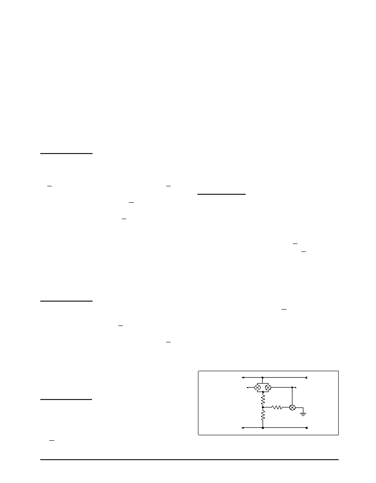
V.35 Receiver
The V. receivers are also used for the
V.35 mode. Unlike the older implementa-
tions of differential receivers used for V.35,
the SP506 contains an internal resistor
termination network that ensures a V.35
input impedance of 00 (+0) and a
short-circuitimpedanceof50(+5). The
traditional V.35 implementations required
external termination resistors to achieve
the proper V.35 impedances. The internal
network is connected via low on-resistance
FET switches when the decoder is changed
to V.35 mode. These FET switches can ac-
cept input signals of up to +5V without any
forward biasing and other parasitic affects.
The V.35 termination resistor network is
switched off when the receiver is disabled
either by the decoder or receiver enable
pin. The termination network is transparent
when all other modes are selected. The V.35
receivers can operate over 20Mbps.
V.11 TERMINATION
MODE [0100]
V.35 MODE
RIN [a]
RIN [b]
To Non-Inverting
Input of Receiver
To Inverting Input
of Receiver
rON = 20
rON = 1
51
124
rON = 1
Figure 51. Simplified R
IN Termination Circuit
相關(guān)PDF資料 |
PDF描述 |
|---|---|
| SP507CM-L | IC TXRX WAN MULTI-MODE 80LQFP |
| SP508EF-L | IC TXRX MULTIPROTOCOL 100LQFP |
| SP510CM-L | IC TXRX MULTIPROTOCOL HS 100LQFP |
| SP526CF-L | IC TXRX WAN MULTI-MODE 44LQFP |
| SP5301CY-L/TR | IC TXRX SERIAL BUS UNIV 14TSSOP |
相關(guān)代理商/技術(shù)參數(shù) |
參數(shù)描述 |
|---|---|
| SP506CM-L | 制造商:Exar Corporation 功能描述:IC WAN MULTIMODE SER TXRX 5.25V LQFP80 |
| SP506EB | 制造商:SIPEX 制造商全稱:Sipex Corporation 功能描述:Multi-Protocol Serial Transceivers |
| SP506EK | 制造商:SIPEX 制造商全稱:Sipex Corporation 功能描述:Multi-Protocol Serial Transceivers |
| SP506RB | 制造商:SIPEX 制造商全稱:Sipex Corporation 功能描述:Multi-Protocol Serial Transceivers |
| SP507 | 制造商:SIPEX 制造商全稱:Sipex Corporation 功能描述:+5V, Single Chip WAN Multi-Mode Serial Transceiver |
發(fā)布緊急采購,3分鐘左右您將得到回復(fù)。