- 您現(xiàn)在的位置:買賣IC網(wǎng) > PDF目錄374788 > SI5320-X-BC (Electronic Theatre Controls, Inc.) SONET/SDH PRECISION CLOCK MULTIPLIER IC PDF資料下載
參數(shù)資料
| 型號: | SI5320-X-BC |
| 廠商: | Electronic Theatre Controls, Inc. |
| 英文描述: | SONET/SDH PRECISION CLOCK MULTIPLIER IC |
| 中文描述: | SONET / SDH的精密時鐘倍頻集成電路 |
| 文件頁數(shù): | 20/34頁 |
| 文件大小: | 538K |
| 代理商: | SI5320-X-BC |
第1頁第2頁第3頁第4頁第5頁第6頁第7頁第8頁第9頁第10頁第11頁第12頁第13頁第14頁第15頁第16頁第17頁第18頁第19頁當(dāng)前第20頁第21頁第22頁第23頁第24頁第25頁第26頁第27頁第28頁第29頁第30頁第31頁第32頁第33頁第34頁
Si5320
20
Rev. 2.3
2.9. Bias Generation Circuitry
The Si5320 makes use of an external resistor to set
internal bias currents. The external resistor allows
precise generation of bias currents which significantly
reduces power consumption and variation as compared
with traditional implementations that use an internal
resistor. The bias generation circuitry requires a 10 k
(1%) resistor connected between REXT and GND.
2.10. Differential Input Circuitry
The Si5320 provides a differential input for the clock
input, CLKIN. This input is internally biased to a voltage
of V
ICM
(see Table 2 on page 6) and may be driven by a
differential or single-ended driver circuit. For differential
transmission lines, the termination resistor is connected
externally as shown.
2.11. Differential Output Circuitry
The Si5320 utilizes a current mode logic (CML)
architecture to drive the differential clock output,
CLKOUT.
For single-ended output operation, simply connect to
either CLKOUT+ or CLKOUT–, and leave the unused
signal unconnected.
2.12. Power Supply Connections
The Si5320 incorporates an on-chip voltage regulator.
The
voltage
regulator
requires
an
external
compensation circuit of one resistor and one capacitor
to ensure stability over all operating conditions.
Internally, the Si5320 V
DD33
pins are connected to the
on-chip voltage regulator input, and the V
DD33
pins also
supply power to the device’s LVTTL I/O circuitry. The
V
DD25
pins supply power to the core DSPLL circuitry
and are also used for connection of the external
compensation circuit.
The regulator’s compensation circuit is in reality a
resistor and a capacitor in series between the V
DD25
node and ground. (See Figure 5 on page 15.) Typically,
the resistor is incorporated into the capacitor’s
equivalent series resistance (ESR). The target RC time
constant for this combination is 15 to 50
μ
s. The
capacitor used in the Si5320 evaluation board is a
33
μ
F tantalum capacitor with an ESR of 0.8
. This
gives an RC time constant of 26.4
μ
s. The Venkel part
number, TA6R3TCR336KBR, is an example of a
capacitor that meets these specs.
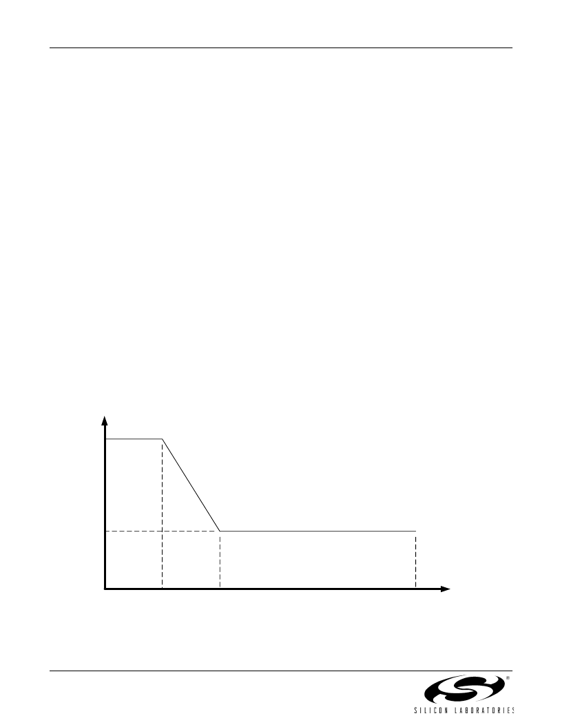
To get optimal performance from the Si5320 device, the
power supply noise spectrum must comply with the plot
in Figure 10. This plot shows the power supply noise
tolerance mask for the Si5320. The customer should
provide a 3.3 V supply that does not have noise density
in excess of the amount shown in the diagram.
However, the diagram cannot be used as spur criteria
for a power supply that contains single tone noise.
Figure 10. Power Supply Noise Tolerance Mask
f
V
n
(
μ
V/
√
Hz)
2100
42
10 kHz
500 kHz
100 Mhz
相關(guān)PDF資料 |
PDF描述 |
|---|---|
| Si5321 | SONET/SDH PRECISION CLOCK MULTIPLIER IC |
| SI5364 | SONET/SDH PRECISION PORT CARD CLOCK IC |
| SI5364-F-BC | SONET/SDH PRECISION PORT CARD CLOCK IC |
| SI5600 | SiPHY-TM OC-192/STM-64 SONET/SDH TRANSCEIVER |
| SI5600-BC | SiPHY-TM OC-192/STM-64 SONET/SDH TRANSCEIVER |
相關(guān)代理商/技術(shù)參數(shù) |
參數(shù)描述 |
|---|---|
| SI5321 | 制造商:未知廠家 制造商全稱:未知廠家 功能描述:SONET/SDH PRECISION CLOCK MULTIPLIER IC |
| SI5321-EVB | 功能描述:時鐘和定時器開發(fā)工具 G.709FEC & 66/64Sc 19-2.5GHz Output RoHS:否 制造商:Texas Instruments 產(chǎn)品:Evaluation Modules 類型:Clock Conditioners 工具用于評估:LMK04100B 頻率:122.8 MHz 工作電源電壓:3.3 V |
| SI5321-F-BC | 功能描述:時鐘合成器/抖動清除器 FOR NEW DESIGNS RoHS:否 制造商:Skyworks Solutions, Inc. 輸出端數(shù)量: 輸出電平: 最大輸出頻率: 輸入電平: 最大輸入頻率:6.1 GHz 電源電壓-最大:3.3 V 電源電壓-最小:2.7 V 封裝 / 箱體:TSSOP-28 封裝:Reel |
| SI5321-G-BC | 功能描述:時鐘發(fā)生器及支持產(chǎn)品 SONET/SDH Precision Clock 19 to 2500MHz RoHS:否 制造商:Silicon Labs 類型:Clock Generators 最大輸入頻率:14.318 MHz 最大輸出頻率:166 MHz 輸出端數(shù)量:16 占空比 - 最大:55 % 工作電源電壓:3.3 V 工作電源電流:1 mA 最大工作溫度:+ 85 C 安裝風(fēng)格:SMD/SMT 封裝 / 箱體:QFN-56 |
| SI5321-G-XC2 | 制造商:Silicon Laboratories Inc 功能描述: |
發(fā)布緊急采購,3分鐘左右您將得到回復(fù)。