- 您現(xiàn)在的位置:買(mǎi)賣(mài)IC網(wǎng) > PDF目錄98079 > SH3001IMLTRT REAL TIME CLOCK, QCC16 PDF資料下載
參數(shù)資料
| 型號(hào): | SH3001IMLTRT |
| 元件分類(lèi): | 時(shí)鐘/數(shù)據(jù)恢復(fù)及定時(shí)提取 |
| 英文描述: | REAL TIME CLOCK, QCC16 |
| 封裝: | 3 X 3 MM, 0.90 MM HEIGHT, LEAD FREE, MLP-16 |
| 文件頁(yè)數(shù): | 16/20頁(yè) |
| 文件大小: | 788K |
| 代理商: | SH3001IMLTRT |
第1頁(yè)第2頁(yè)第3頁(yè)第4頁(yè)第5頁(yè)第6頁(yè)第7頁(yè)第8頁(yè)第9頁(yè)第10頁(yè)第11頁(yè)第12頁(yè)第13頁(yè)第14頁(yè)第15頁(yè)當(dāng)前第16頁(yè)第17頁(yè)第18頁(yè)第19頁(yè)第20頁(yè)

SH3001 MicroBuddy
SYSTEM MANAGEMENT
Copyright 2002-2005 Semtech Corporation
5
V1.15
www.semtech.com
Clock Management System
The SH3001 provides a flexible tool for creating and
managing clocks, a versatile and accurate “any
frequency” clock synthesizer (see Figure 1).
It is capable of generating any frequency in the
range of 62.5 kHz to 16.0 MHz, with worst-case
resolution of 0.0256% (256 ppm). The internal
32.768 kHz clock can also be routed to the CLKOUT pin
(and HF oscillator stopped for energy savings).
The objectives, features, and behavior of the Clock
Management System are aimed towards the systems
that utilize a microcontroller, a microprocessor, a DSP or
an ASIC.
The SH3001 permits the automatic sensing of the
intentions of the host processor, an industry first. The
SH3001 shuts down its clock output when it senses that
the host processor issued a STOP instruction.
Subsequently, the SH3001 idles, consuming less than
10 A. As soon as the host exits the STOP mode, the
SH3001 instantaneously starts to supply a stable clock
(<2s wake-up).
A typical system, constructed with a ceramic
resonator or a crystal as the frequency determining
element, must wait at least several hundred
microseconds (for a resonator), or as much as 100 ms or
more (for a HF crystal), to re-start the oscillator. The
SH3001 allows the response to and service of an event
to finish with a speed previously unattainable for a
simple microprocessor. A system with a traditional clock
approach can be as much as 100x – 10,000x slower.
Clock Generator Operation
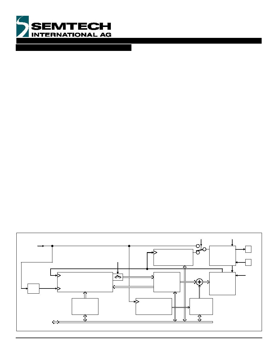
The frequency synthesizer in the SH3001 is
constructed from the 2:1 tunable 8.0 –16.0 MHz HF
oscillator followed by a programmable “power-of-two”
post-divider (see Figure 1).
The Clock Source selector and the programmable
post-scale divider allow instantaneous switching
between the 32.768 kHz internal clock and divided-down
HF oscillator output. There is no settling or instability
when the switch occurs.
This is a preferred method for clock control in
computing systems, when the large ratio between high
and low frequency of operations allows for
correspondingly large and instantaneous savings in
power consumption.
Post-scaler
(Divide by 1, 2, 4,
8, 16, 32, 64, 128)
Figure 1. Simplified HF Oscillator System
32.768 kHz
START/STOP
16
15
CLKOUT
CLKIN
Clock Buffer
and Glue
Logic
HF Digitally
Controlled
Oscillator
8-16 MHz
18-bit
DCO Code
Register
Clock On
Force
DCO On
Clock Source
1
0
Spectrum
Spreading
Controls
Frequency Locked Loop
Logic
13-bit
Frequency
Set value
÷ 16 2048 Hz
8-bit Pseudo-
Random Noise
Generator
FLL On
From / To
Serial I/O
相關(guān)PDF資料 |
PDF描述 |
|---|---|
| SH3001IMLTR | REAL TIME CLOCK, QCC16 |
| SH703600FG | SPECIALTY MICROPROCESSOR CIRCUIT, PQFP32 |
| SH7041 | MROM, RISC MICROCONTROLLER, PQFP144 |
| SH7702 | 32-BIT, 45 MHz, RISC PROCESSOR, PQFP120 |
| SH7708S | 32-BIT, RISC MICROCONTROLLER, PQFP144 |
相關(guān)代理商/技術(shù)參數(shù) |
參數(shù)描述 |
|---|---|
| SH3002 | 制造商:SEMTECH 制造商全稱(chēng):Semtech Corporation 功能描述:Reset Management and Clock Management Support IC for Microcontrollers |
| SH3002-DC70A | 制造商:ROHM 制造商全稱(chēng):Rohm 功能描述:Near edge thermal printhead (with thermal historical control) |
| SH3002-DC80A | 制造商:ROHM 制造商全稱(chēng):Rohm 功能描述:Near edge thermal printhead (with thermal historical control) |
| SH3002-DC90A | 制造商:ROHM 制造商全稱(chēng):Rohm 功能描述:Near edge type thermal printhead(11.81dots / mm) |
| SH3002-DC90A_09 | 制造商:ROHM 制造商全稱(chēng):Rohm 功能描述:Near edge type thermal printhead(11.81dots / mm) |
發(fā)布緊急采購(gòu),3分鐘左右您將得到回復(fù)。