- 您現(xiàn)在的位置:買賣IC網(wǎng) > PDF目錄374768 > SED1336F (Electronic Theatre Controls, Inc.) LCD Controller ICs PDF資料下載
參數(shù)資料
| 型號: | SED1336F |
| 廠商: | Electronic Theatre Controls, Inc. |
| 英文描述: | LCD Controller ICs |
| 中文描述: | LCD控制器芯片 |
| 文件頁數(shù): | 81/148頁 |
| 文件大?。?/td> | 388K |
| 代理商: | SED1336F |
第1頁第2頁第3頁第4頁第5頁第6頁第7頁第8頁第9頁第10頁第11頁第12頁第13頁第14頁第15頁第16頁第17頁第18頁第19頁第20頁第21頁第22頁第23頁第24頁第25頁第26頁第27頁第28頁第29頁第30頁第31頁第32頁第33頁第34頁第35頁第36頁第37頁第38頁第39頁第40頁第41頁第42頁第43頁第44頁第45頁第46頁第47頁第48頁第49頁第50頁第51頁第52頁第53頁第54頁第55頁第56頁第57頁第58頁第59頁第60頁第61頁第62頁第63頁第64頁第65頁第66頁第67頁第68頁第69頁第70頁第71頁第72頁第73頁第74頁第75頁第76頁第77頁第78頁第79頁第80頁當(dāng)前第81頁第82頁第83頁第84頁第85頁第86頁第87頁第88頁第89頁第90頁第91頁第92頁第93頁第94頁第95頁第96頁第97頁第98頁第99頁第100頁第101頁第102頁第103頁第104頁第105頁第106頁第107頁第108頁第109頁第110頁第111頁第112頁第113頁第114頁第115頁第116頁第117頁第118頁第119頁第120頁第121頁第122頁第123頁第124頁第125頁第126頁第127頁第128頁第129頁第130頁第131頁第132頁第133頁第134頁第135頁第136頁第137頁第138頁第139頁第140頁第141頁第142頁第143頁第144頁第145頁第146頁第147頁第148頁
S-MOS Systems, Inc. 2460 North First Street San Jose, CA 95131 Tel: (408) 922-0200 Fax: (408) 922-0238
268-0.4
81
5.2 – 5.2.2
5.0 Display Control Functions
5.2 Screen Configuration
5.2.1 Screen Configuration
The basic screen configuration of the SED1330F/
1335F/1336F is as a single text screen or as overlap-
ping text and graphics screens. The graphics screen
uses eight times as much display memory as the text
screen.
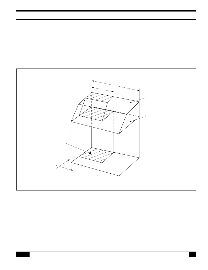
A/P
Character
memory area
Graphics
memory area
(XM,YM)
(XM,0)
(0,0)
(0,YM)
(XW,YM)
0800H
0000H
Display
memory
window
07FFH
47FFH
C/R
Y
X
Figure 48. Virtual and physical screen relationship
5.2.2 Display Address Scanning
The SED1330F/1335F/1336F scans the display memory
in the same way as a raster scan CRT screen. Each row
is scanned from left to right until the address range
equals C/R. Rows are scanned from top to bottom.
In graphics mode, at the start of each line, the address
counter is set to the address at the start of the previous
line plus the address pitch, AP.
In text mode, the address counter is set to the same
start address, and the same character data is read, for
each row in the character bitmap. However, a new row
of the character generator output is used each time.
Once all the rows in the character bitmap have been
displayed, the address counter is set to the start
address plus AP and the next line of text is displayed.
Figure 40 shows the relationship between the virtual
screens and the physical screen.
相關(guān)PDF資料 |
PDF描述 |
|---|---|
| SED1500 | DOT MATRIX LCD DRIVER |
| SED1501 | DOT MATRIX LCD DRIVER |
| SED1502 | DOT MATRIX LCD DRIVER |
| SED1503 | DOT MATRIX LCD DRIVER |
| SED1520 | DOT MATRIX LCD DRIVER |
相關(guān)代理商/技術(shù)參數(shù) |
參數(shù)描述 |
|---|---|
| SED1351 | 制造商:未知廠家 制造商全稱:未知廠家 功能描述:GRAPHICS LCD CONTROLLER |
| SED1351F | 制造商:未知廠家 制造商全稱:未知廠家 功能描述:CMOS GRAPHIC LCD CONTROLLER |
| SED1351F0A | 制造商:Seiko Instruments Inc (SII) 功能描述: |
| SED1352 | 制造商:EPSON 制造商全稱:EPSON 功能描述:Document Number: X16B-Q-001-06 |
| SED1353 | 制造商:EPSON 制造商全稱:EPSON 功能描述:SED1353 GRAPHICS LCD CONTROLLER |
發(fā)布緊急采購,3分鐘左右您將得到回復(fù)。