- 您現(xiàn)在的位置:買賣IC網(wǎng) > PDF目錄359757 > S29GL128P10TAIV10 (SPANSION LLC) 3.0 Volt-only Page Mode Flash Memory featuring 90 nm MirrorBit Process Technology PDF資料下載
參數(shù)資料
| 型號: | S29GL128P10TAIV10 |
| 廠商: | SPANSION LLC |
| 元件分類: | DRAM |
| 英文描述: | 3.0 Volt-only Page Mode Flash Memory featuring 90 nm MirrorBit Process Technology |
| 中文描述: | 128M X 1 FLASH 3V PROM, 100 ns, PDSO56 |
| 封裝: | 20 X 14 MM, MO-142EC, TSOP-56 |
| 文件頁數(shù): | 28/77頁 |
| 文件大小: | 2121K |
| 代理商: | S29GL128P10TAIV10 |
第1頁第2頁第3頁第4頁第5頁第6頁第7頁第8頁第9頁第10頁第11頁第12頁第13頁第14頁第15頁第16頁第17頁第18頁第19頁第20頁第21頁第22頁第23頁第24頁第25頁第26頁第27頁當(dāng)前第28頁第29頁第30頁第31頁第32頁第33頁第34頁第35頁第36頁第37頁第38頁第39頁第40頁第41頁第42頁第43頁第44頁第45頁第46頁第47頁第48頁第49頁第50頁第51頁第52頁第53頁第54頁第55頁第56頁第57頁第58頁第59頁第60頁第61頁第62頁第63頁第64頁第65頁第66頁第67頁第68頁第69頁第70頁第71頁第72頁第73頁第74頁第75頁第76頁第77頁
28
S29GL-P MirrorBit
Flash Family
S29GL-P_00_A7 November 8, 2007
D a t a
S h e e t
( P r e l i m i n a r y )
Software Functions and Sample Code
Notes
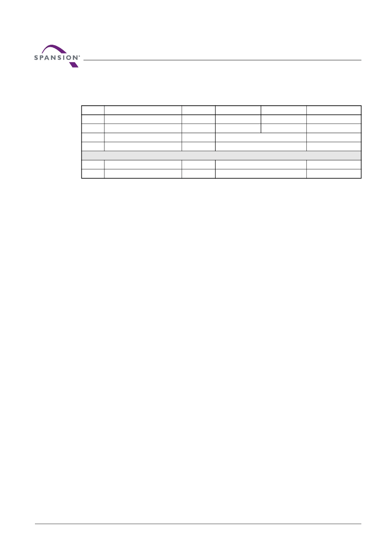
1. Base = Base Address.
2. Last = Last cycle of write buffer program operation; depending on number of words written, the total number of cycles may be from 6 to
37.
3. For maximum efficiency, it is recommended that the write buffer be loaded with the highest number of words (N words) possible.
The following is a C source code example of using the write buffer program function. Refer to the
Spansion
Low Level Driver User’s Guide
(available on
www.spansion.com
) for general information on Spansion Flash
memory software development guidelines.
/* Example: Write Buffer Programming Command */
/* NOTES: Write buffer programming limited to 16 words. */
/* All addresses to be written to the flash in */
/* one operation must be within the same flash */
/* page. A flash page begins at addresses */
/* evenly divisible by 0x20. */
UINT16 *src = source_of_data; /* address of source data */
UINT16 *dst = destination_of_data; /* flash destination address */
UINT16 wc = words_to_program -1; /* word count (minus 1) */
*( (UINT16 *)base_addr + 0x555 ) = 0x00AA; /* write unlock cycle 1 */
*( (UINT16 *)base_addr + 0x2AA ) = 0x0055; /* write unlock cycle 2 */
*( (UINT16 *)sector_address ) = 0x0025; /* write write buffer load command */
*( (UINT16 *)sector_address ) = wc; /* write word count (minus 1) */
for (i=0;i<=wc;i++)
{
*dst++ = *src++; /* ALL dst MUST BE in same Write Buffer */
}
*( (UINT16 *)sector_address ) = 0x0029; /* write confirm command */
/* poll for completion */
/* Example: Write Buffer Abort Reset */
*( (UINT16 *)addr + 0x555 ) = 0x00AA; /* write unlock cycle 1 */
*( (UINT16 *)addr + 0x2AA ) = 0x0055; /* write unlock cycle 2 */
*( (UINT16 *)addr + 0x555 ) = 0x00F0; /* write buffer abort reset */
Table 7.7
Write Buffer Program
(LLD Functions Used = lld_WriteToBufferCmd, lld_ProgramBufferToFlashCmd)
Cycle
Description
Operation
Byte Address
Word Address
Data
1
Unlock
Write
Base + AAAh
Base + 555h
00AAh
2
Unlock
Write
Base + 555h
Base + 2AAh
0055h
3
Write Buffer Load Command
Write
Sector Address
0025h
4
Write Word Count
Write
Sector Address
Word Count (N–1)h
Number of words (N) loaded into the write buffer can be from 1 to 32 words (1 to 64 bytes).
5 to 36
Load Buffer Word N
Write
Program Address, Word N
Word N
Last
Write Buffer to Flash
Write
Sector Address
0029h
相關(guān)PDF資料 |
PDF描述 |
|---|---|
| S29GL128P90TFIV12 | 3.0 Volt-only Page Mode Flash Memory featuring 90 nm MirrorBit Process Technology |
| STK435-xxx | THICK FILM HYBRID IC |
| STK436-xxx | THICK FILM HYBRID IC |
| STK437-xxx | THICK FILM HYBRID IC |
| STK439-xxx | THICK FILM HYBRID IC |
相關(guān)代理商/技術(shù)參數(shù) |
參數(shù)描述 |
|---|---|
| S29GL128P10TFI010 | 功能描述:閃存 128Mb 3V 110ns Parallel NOR 閃存 RoHS:否 制造商:ON Semiconductor 數(shù)據(jù)總線寬度:1 bit 存儲類型:Flash 存儲容量:2 MB 結(jié)構(gòu):256 K x 8 定時(shí)類型: 接口類型:SPI 訪問時(shí)間: 電源電壓-最大:3.6 V 電源電壓-最小:2.3 V 最大工作電流:15 mA 工作溫度:- 40 C to + 85 C 安裝風(fēng)格:SMD/SMT 封裝 / 箱體: 封裝:Reel |
| S29GL128P10TFI010 | 制造商:Spansion 功能描述:IC SM FLASH 3V 128MB 100NS |
| S29GL128P10TFI010-AU | 制造商:Spansion 功能描述:SPZS29GL128P10TFI010-AU IC 128M PAGE-MO |
| S29GL128P10TFI012 | 制造商:Spansion 功能描述:IC 128M PAGE-MODE FLASH MEMORY - Trays |
| S29GL128P10TFI013 | 制造商:Spansion 功能描述:FLASH PARALLEL 3V/3.3V 128MBIT 16MX8/8MX16 100NS 56TSOP - Tape and Reel |
發(fā)布緊急采購,3分鐘左右您將得到回復(fù)。