- 您現(xiàn)在的位置:買賣IC網(wǎng) > PDF目錄374572 > RC5061M (FAIRCHILD SEMICONDUCTOR CORP) Current-Mode SMPS Controller PDF資料下載
參數(shù)資料
| 型號(hào): | RC5061M |
| 廠商: | FAIRCHILD SEMICONDUCTOR CORP |
| 元件分類: | 穩(wěn)壓器 |
| 英文描述: | Current-Mode SMPS Controller |
| 中文描述: | SWITCHING CONTROLLER, 345 kHz SWITCHING FREQ-MAX, PDSO20 |
| 封裝: | SOIC-20 |
| 文件頁數(shù): | 13/18頁 |
| 文件大?。?/td> | 135K |
| 代理商: | RC5061M |
PRODUCT SPECIFICATION
RC5061
REV. 1.0.0 7/6/00
13
Design Considerations and Component
Selection
Additional information on design and component selection
may be found in Fairchild’s Application Note 57.
MOSFET Selection
This application requires N-channel Logic Level Enhancement
Mode Field Effect Transistors. Desired characteristics are as
follows:
Low Static Drain-Source On-Resistance, R
DS,ON
< 20m
(lower is better)
Low gate drive voltage, V
GS
= 4.5V rated
Power package with low Thermal Resistance
Drain-Source voltage rating > 15V.
The on-resistance (R
DS,ON)
is the primary parameter for
MOSFET selection. The on-resistance determines the power
dissipation within the MOSFET and therefore significantly
affects the efficiency of the DC-DC Converter. For details
and a spreadsheet on MOSFET selection, refer to Applica-
tions Bulletin AB-8.
Inductor Selection
Choosing the value of the inductor is a tradeoff between
allowable ripple voltage and required transient response. The
system designer can choose any value within the allowed
minimum to maximum range in order to either minimize ripple
or maximize transient performance. The first order equation
(close approximation) for minimum inductance is:
where:
V
in
= Input Power Supply
V
out
= Output Voltage
f = DC/DC converter switching frequency
ESR = Equivalent series resistance of all output capacitors in
parallel
V
ripple
= Maximum peak to peak output ripple voltage budget.
The first order equation for maximum allowed inductance is:
where:
C
o
= The total output capacitance
I
pp
= Maximum to minimum load transient current
V
tb
= The output voltage tolerance budget allocated to load
transient
D
m
= Maximum duty cycle for the DC/DC converter (usually
95%).
Some margin should be maintained away from both L
min
and
L
max
. Adding margin by increasing L almost always adds
expense since all the variables are predetermined by system
performance except for C
O
, which must be increased to
increase L. Adding margin by decreasing L can be done by
purchasing capacitors with lower ESR. The RC5061 pro-
vides significant cost savings for the newer CPU systems
that typically run at high supply current.
RC5061 Short Circuit Current Characteristics
The RC5061 protects against output short circuit on the core
supply by turning off both the high-side and low-side
MOSFETs and resetting softstart. The short circuit limit is
set with the R
S
resistor, as given by the formula
with I
Detect
≈
50μA, I
SC
is the desired current limit, and
R
DS,on
the high-side MOSFET’s on resistance. Remember to
make the R
S
large enough to include the effects of initial tol-
erance and temperature variation on the MOSFET’s R
DS,on
.
Alternately, use of a sense resistor in series with the source
of the MOSFET eliminates this source of inaccuracy in the
current limit. The value of R
S
should be less than 8.3K
. If a
greater value is necessary, a lower R
DS,on
MOSFET should
be used instead.
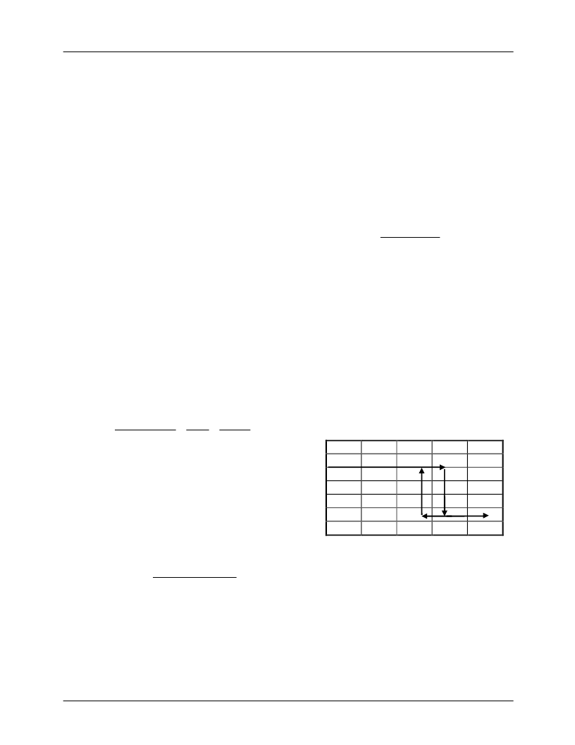
As an example, Figure 4 shows the typical characteristic of
the DC-DC converter circuit with an FDB6030L high-side
MOSFET (R
DS
= 20m
maximum at 25°C * 1.25 at 75°C =
25m
) and a 8.2K
R
S
.
Figure 4. RC5061 Short Circuit Characteristic
The converter exhibits a normal load regulation characteristic
until the voltage across the MOSFET exceeds the internal
short circuit threshold of 50μA * 8.2K
= 410mV, which
occurs at 410mV/25m
= 16.4A. (Note that this current limit
level can be as high as 410mV/15m
= 27A, if the MOSFET
has typical R
DS,on
rather than maximum, and is at 25°C).
At this point, the internal comparator trips and signals the con-
troller to discharge the softstart capacitor. This causes a drastic
reduction in the output voltage as the load regulation collapses
into the short circuit control mode. With a 40m
output short,
L
min
(Vin
–
V
out
)
f
x
V
out
V
in
x
ESR
V
ripple
=
L
max
(Vin
–
V
out
) D
m
V
tb
I
pp2
= 2C
O
R
S
I
SC
*R
DS, on
I
Detect
=
V
O
(
0 5 10 15 20 25
3.5
3.0
2.5
2.0
1.5
1.0
0.5
0
CPU Output Voltage vs. Output Current
相關(guān)PDF資料 |
PDF描述 |
|---|---|
| RC5532 | High Performance Dual Low Noise Operational Amplifier |
| RC5532A | High Performance Dual Low Noise Operational Amplifier |
| RC5532AD | High Performance Dual Low Noise Operational Amplifier |
| RC5532AN | High Performance Dual Low Noise Operational Amplifier |
| RC5532D | High Performance Dual Low Noise Operational Amplifier |
相關(guān)代理商/技術(shù)參數(shù) |
參數(shù)描述 |
|---|---|
| RC5061MT | 功能描述:開關(guān)變換器、穩(wěn)壓器與控制器 SOIC-20 RoHS:否 制造商:Texas Instruments 輸出電壓:1.2 V to 10 V 輸出電流:300 mA 輸出功率: 輸入電壓:3 V to 17 V 開關(guān)頻率:1 MHz 工作溫度范圍: 安裝風(fēng)格:SMD/SMT 封裝 / 箱體:WSON-8 封裝:Reel |
| RC5-1/133 | 制造商:ABB Low Voltage Products and Systems 功能描述:A9-A40,SS,RC,50-133V |
| RC5-1/250 | 制造商:ABB Low Voltage Products and Systems 功能描述:A9-A40,SS,RC,110-250V |
| RC5-10-01-H-D-0.41-D | 制造商:Samtec Inc 功能描述:IP68 TIGER EYE SEALED CABLE PLUG - Bulk |
| RC5-10-01-H-D-00.25-BC | 制造商:Samtec Inc 功能描述:IP68 TIGER EYE SEALED CABLE PLUG - Bulk |
發(fā)布緊急采購,3分鐘左右您將得到回復(fù)。