- 您現(xiàn)在的位置:買賣IC網(wǎng) > PDF目錄382380 > PCD5003AH (NXP SEMICONDUCTORS) Enhanced Pager Decoder for POCSAG PDF資料下載
參數(shù)資料
| 型號(hào): | PCD5003AH |
| 廠商: | NXP SEMICONDUCTORS |
| 元件分類: | 尋呼電路 |
| 英文描述: | Enhanced Pager Decoder for POCSAG |
| 中文描述: | TELECOM, PAGING DECODER, PQFP32 |
| 封裝: | 7 X 7 MM, 1.40 MM HEIGHT, PLASTIC, SOT-358-1, LQFP-32 |
| 文件頁(yè)數(shù): | 7/44頁(yè) |
| 文件大?。?/td> | 233K |
| 代理商: | PCD5003AH |
第1頁(yè)第2頁(yè)第3頁(yè)第4頁(yè)第5頁(yè)第6頁(yè)當(dāng)前第7頁(yè)第8頁(yè)第9頁(yè)第10頁(yè)第11頁(yè)第12頁(yè)第13頁(yè)第14頁(yè)第15頁(yè)第16頁(yè)第17頁(yè)第18頁(yè)第19頁(yè)第20頁(yè)第21頁(yè)第22頁(yè)第23頁(yè)第24頁(yè)第25頁(yè)第26頁(yè)第27頁(yè)第28頁(yè)第29頁(yè)第30頁(yè)第31頁(yè)第32頁(yè)第33頁(yè)第34頁(yè)第35頁(yè)第36頁(yè)第37頁(yè)第38頁(yè)第39頁(yè)第40頁(yè)第41頁(yè)第42頁(yè)第43頁(yè)第44頁(yè)

1999 Jan 08
7
Philips Semiconductors
Product specification
Enhanced Pager Decoder for POCSAG
PCD5003A
Alert-only calls only consist of a single address code-word.
Numeric and alphanumeric calls have message
code-words following the address. A message causes the
frame structure to be temporarily suspended. Message
code-words are sent until the message is completed, with
only the sync words being transmitted in their expected
positions.
Message
code-words are identified by an MSB of logic 1
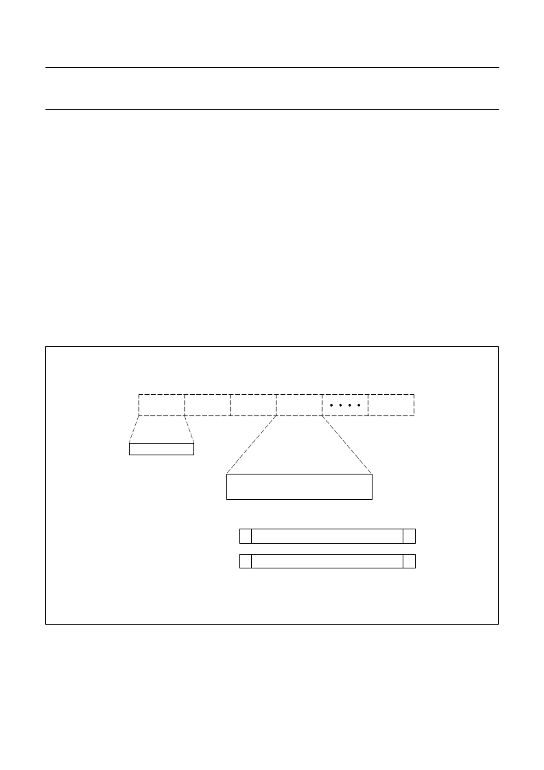
and are coded as shown in Fig.3. The message
information is stored in a 20-bit field (bits 2 to 21). The data
format is determined by the call type: 4 bits per digit for
numeric messages and 7 bits per (ASCII) character for
alphanumeric messages.
Each code-word is protected against transmission errors
by 10 CRC check bits (bits 22 to 31) and an even-parity bit
(bit 32). This permits correction of maximum 2 random
errors or up to 3 errors in a burst of 4 bits (a 4-bit burst
error) per code-word.
The POCSAG standard recommends the use of
combinations of data formats and function bits, as given in
Table 1. Other (non-standard) combinations will be
received normally by the PCD5003A. Message data is not
deformatted.
In the PCD5003A error correction methods have been
implemented as shown in Table 2.
Random error correction is default for both address and
message code-words. In addition, burst error correction
can be enabled by SPF programming. Up to 3 erroneous
bits in a 4-bit burst can be corrected.
The error type detected for each code-word is identified in
the message data output to the microcontroller, allowing
rejection of calls with too many errors.
Fig.3 POCSAG code structure.
handbook, full pagewidth
PREAMBLE
BATCH 1
BATCH 2
BATCH 3
LAST BATCH
SYNC | CW CW | CW CW | . . . . . | CW CW
FRAME 0
FRAME 1
FRAME 7
10101 . . . 10101010
Address code-word
Message code-word
0
18-bit address
2 function bits
10 CRC bits
P
1
20-bit message
10 CRC bits
P
MCD456
相關(guān)PDF資料 |
PDF描述 |
|---|---|
| PCD5003 | Advanced POCSAG Paging Decoder |
| PCD5003H | Advanced POCSAG Paging Decoder |
| PCD5008 | FLEX Pager Decoder |
| PCD5008H | FLEX Pager Decoder |
| PCD5013 | FLEX roaming decoder II |
相關(guān)代理商/技術(shù)參數(shù) |
參數(shù)描述 |
|---|---|
| PCD5003H | 制造商:PHILIPS 制造商全稱:NXP Semiconductors 功能描述:Advanced POCSAG Paging Decoder |
| PCD5003HB-T | 制造商:未知廠家 制造商全稱:未知廠家 功能描述:Telecommunication Decoder |
| PCD5003U/10 | 制造商:PHILIPS 制造商全稱:NXP Semiconductors 功能描述:Advanced POCSAG Paging Decoder |
| PCD5008 | 制造商:PHILIPS 制造商全稱:NXP Semiconductors 功能描述:FLEX Pager Decoder |
| PCD5008H | 制造商:PHILIPS 制造商全稱:NXP Semiconductors 功能描述:FLEX Pager Decoder |
發(fā)布緊急采購(gòu),3分鐘左右您將得到回復(fù)。