- 您現(xiàn)在的位置:買賣IC網(wǎng) > PDF目錄383642 > MT8930B (Mitel Networks Corporation) () PDF資料下載
參數(shù)資料
| 型號: | MT8930B |
| 廠商: | Mitel Networks Corporation |
| 英文描述: | () |
| 中文描述: | () |
| 文件頁數(shù): | 3/29頁 |
| 文件大小: | 277K |
| 代理商: | MT8930B |
第1頁第2頁當(dāng)前第3頁第4頁第5頁第6頁第7頁第8頁第9頁第10頁第11頁第12頁第13頁第14頁第15頁第16頁第17頁第18頁第19頁第20頁第21頁第22頁第23頁第24頁第25頁第26頁第27頁第28頁第29頁
Application Note
MSAN-141
A-203
1.0 MT8930B/31B S/T-Interface
Transceiver
The MT8930B/31B Subscriber Network Interface
Circuit (SNIC) is a multifunction transceiver providing
a complete interface to the S/T Reference Point as
specified in CCITT Recommendation I.430 and ANSI
T1.605. Implementing both point-to-point and
point-to- multipoint voice/data transmission, the
SNIC may be used at either end of the digital
subscriber loop. A programmable digital interface
allows the MT8930B/31B to be configured as a
Network Termination (NT) or as a Terminal
Equipment (TE) device.
The physical medium for the S-interface is a
balanced line for each direction of transmission
capable of supporting 192 kbit/s which will now be
referred to as the S-Bus. This transmission facility is
time division multiplexed in order to carry 2 x 64
kbit/s B-channels and 1 x 16 kbit/s D-channel.
Transmission capability for both B and D channels,
as well as related timing and synchronization
functions, are provided on chip. The signalling
capability and procedures necessary to enable
customer terminals (TEs) to be activated and
deactivated form part of the MT8930B/31B’s
functionality. The SNIC handles D-channel resource
allocation and prioritization for access contention
resolution and signalling requirements in passive bus
line configurations. Control and status information
allows implementation of maintenance functions and
monitoring of the device and the subscriber loop.
An HDLC transceiver is included on the SNIC for link
access protocol handling via the D-channel.
Depacketized data is passed to and from the
transceiver via the microprocessor port. Two 19 byte
deep FIFOs, one for transmit and one for receive, are
provided to buffer the data. The HDLC block can be
set up to transmit or receive to/from either the
S-interface port or the ST-BUS port. Further, the
transmit destination and receive source can be
independently selected, e.g., transmit to S-interface
while receiving from ST-BUS. The transmit and
receive paths can be separately enabled or disabled.
Both one and two byte address recognition is
supported by the SNIC. A transparent mode allows
data to be passed directly to the D-channel without
being packetized.
The MT8930B provides a controllerless mode which
eliminates the need for a microprocessor. The TE
mode in the MT8930B is selected by tying pin 8 to
ground, or to a 4.096 MHz clock. On the other hand,
the MT8931B doesn’t offer a controllerless mode, but
its TE mode is selected by either tying pin 8 to a
4.096 MHz clock or to a crystal connected between
pin 8 and pin 7.
The MT8930B is recommended as a replacement for
the MT8930 in existing systems, or for new
proprietary applications where CCITT and ANSI
standards don’t have to be fully met. In such cases,
customers may operate the MT8930B in TE mode
without the use of an external clock, therefore,
saving the added cost of an external oscillator.
The MT8931B, on the other hand, is recommended
for new designs requiring full compatibility with
CCITT and ANSI standards. The MT8931B will
operate in TE mode with just a crystal, as compared
to an oscillator for the MT8930B.
2.0 Access Considerations at the S-
Interface
2.1
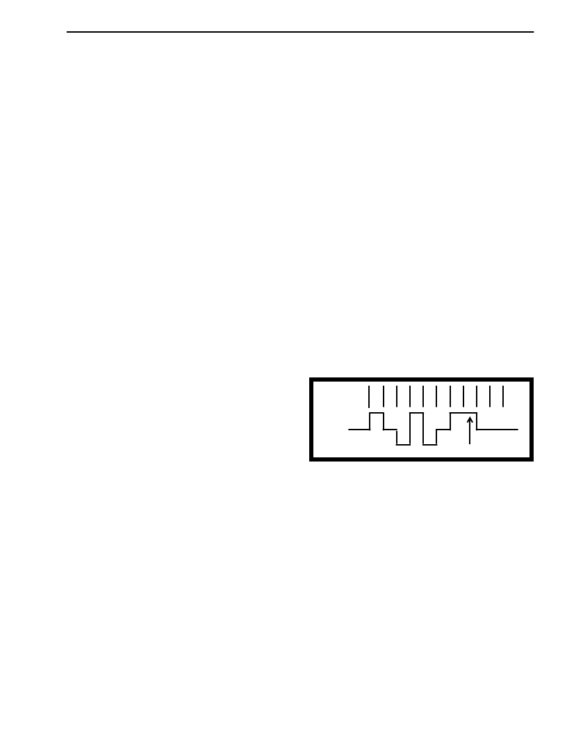
Line Code
The line code used on the S-interface is a pseudo
ternary code with 100% pulse width as shown in
Figure 2 below. Binary zeros are represented as
marks on the line and successive marks will
alternate in polarity. A mark which does not adhere
to the alternating polarity is known as a bipolar
violation.
Figure 2 - Alternate Zero Code Inversion Line
2.2
Frame Structure
A valid S-Bus frame consists of 48 bits transmitted at
the nominal bit rate of 192 kbit/s. This gives a 4 kHz
S-Bus frame of which each B- or D-channel will
consume two valid timeslots. The frame is struc-
tured using various bits which are used as follows:
F-bit:
The F-bit is used to delimit the S-Bus frame
boundary. The F-bit is positioned at the
beginning of the frame and it can be iden-
tified very quickly because it will always be a
mark which will violate the alternate line code
sequence. (i.e., F-bit is a violation).
Fa-bit: The Fa-bit is the auxiliary framing bit. It is
used to secure the frame position in the
presence of an idle B- and D-channel
following the F-bit. The Fa and N bits can
BINARY
VALUE
LINE
SIGNAL
Violation
0
1
0
0
0
1
0
0
1
1
相關(guān)PDF資料 |
PDF描述 |
|---|---|
| MT8931B | () |
| MT8930C-1 | SWITCH, ON-OFF, CHROM/BLK BTN; Switch function type:SPST Latching; Voltage, contact AC max:125V; Voltage, contact DC max:24V; Temp, op. max:85(degree C); Temp, op. min:-40(degree C); Diameter, panel cut-out:13.6mm; Length / Height, RoHS Compliant: Yes |
| MT8930C | Subscriber Network Interface Circuit(用戶網(wǎng)絡(luò)接口電路(提供點到點或點到多點數(shù)字傳送)) |
| MT8930 | CMOS ST-BUS⑩ FAMILY Subscriber Network Interface Circuit Preliminary Information |
| MT8930C | CMOS ST-BUS⑩ FAMILY Subscriber Network Interface Circuit Preliminary Information |
相關(guān)代理商/技術(shù)參數(shù) |
參數(shù)描述 |
|---|---|
| MT8930BC | 制造商:MITEL 制造商全稱:Mitel Networks Corporation 功能描述:Subscriber Network Interface Circuit |
| MT8930BE | 制造商:MITEL 制造商全稱:Mitel Networks Corporation 功能描述:Subscriber Network Interface Circuit |
| MT8930BP | 制造商:MITEL 制造商全稱:Mitel Networks Corporation 功能描述:Subscriber Network Interface Circuit |
| MT8930C | 制造商:ZARLINK 制造商全稱:Zarlink Semiconductor Inc 功能描述:Subscriber Network Interface Circuit |
| MT8930C-1 | 制造商:MITEL 制造商全稱:Mitel Networks Corporation 功能描述:CMOS ST-BUS⑩ FAMILY Subscriber Network Interface Circuit |
發(fā)布緊急采購,3分鐘左右您將得到回復(fù)。