- 您現(xiàn)在的位置:買賣IC網(wǎng) > PDF目錄371132 > MP1570DN (MONOLITHIC POWER SYSTEMS INC) 3A, 23V, 340KHz Synchronous Rectified Step-Down Converter PDF資料下載
參數(shù)資料
| 型號: | MP1570DN |
| 廠商: | MONOLITHIC POWER SYSTEMS INC |
| 元件分類: | 穩(wěn)壓器 |
| 英文描述: | 3A, 23V, 340KHz Synchronous Rectified Step-Down Converter |
| 中文描述: | 3 A SWITCHING REGULATOR, 380 kHz SWITCHING FREQ-MAX, PDSO8 |
| 封裝: | SOIC-8 |
| 文件頁數(shù): | 6/11頁 |
| 文件大小: | 333K |
| 代理商: | MP1570DN |
MP1570 – 3A, 23V, 340KHz SYNCHRONOUS RECTIFIED, STEP-DOWN CONVERTER
MP1570 Rev. 1.5
1/31/2006
www.MonolithicPower.com
6
MPS Proprietary Information. Unauthorized Photocopy and Duplication Prohibited.
2006 MPS. All Rights Reserved.
TM
peak inductor current is below the maximum
switch current limit. The inductance value can
be calculated by:
×
×
=
IN
OUT
V
S
OUT
V
V
1
I
f
L
Where V
IN
is the input voltage, f
S
is the 340KHz
switching frequency, and
I
L
is the peak-to-
peak inductor ripple current.
Choose an inductor that will not saturate under
the maximum inductor peak current. The peak
inductor current can be calculated by:
×
×
×
+
=
IN
OUT
V
S
OUT
f
LOAD
LP
I
V
1
L
2
V
I
Where I
LOAD
is the load current.
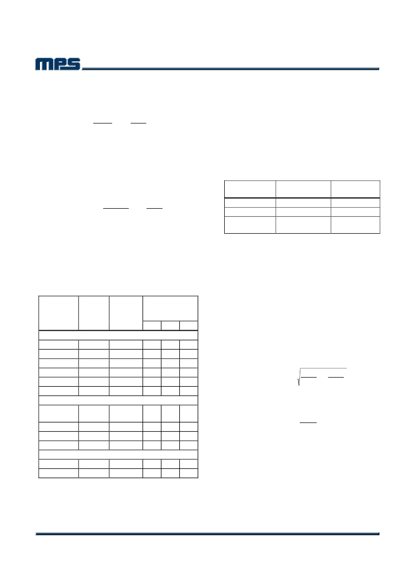
Table 1 lists a number of suitable inductors
from various manufacturers. The choice of
which style inductor to use mainly depends on
the price vs. size requirements and any EMI
requirement.
Table 1—Inductor Selection Guide
Package
Dimensions
(mm)
W
L
Vendor/
Model
Sumida
CR75
CDH74
CDRH5D28 Shielded
CDRH5D28 Shielded
CDRH6D28 Shielded
CDRH104R Shielded
Toko
D53LC
Type A
D75C
D104C
D10FL
Coilcraft
DO3308
DO3316
Core
Type
Core
Material
H
Open
Open
Ferrite
Ferrite
Ferrite
Ferrite
Ferrite
Ferrite
7.0
7.3
5.5
5.5
6.7
10.1 10.0
7.8
8.0
5.7
5.7
6.7
5.5
5.2
5.5
5.5
3.0
3.0
Shielded
Ferrite
5.0
5.0
3.0
Shielded
Shielded
Open
Ferrite
Ferrite
Ferrite
7.6
10.0 10.0
9.7
7.6
5.1
4.3
4.0
1.5
Open
Open
Ferrite
Ferrite
9.4 13.0
9.4 13.0
3.0
5.1
Optional Schottky Diode
During the transition between high-side switch
and low-side switch, the body diode of the low-
side power MOSFET conducts the inductor
current. The forward voltage of this body diode
is high. An optional Schottky diode may be
paralleled between the SW pin and GND pin to
improve overall efficiency. Table 2 lists example
Schottky diodes and their Manufacturers.
Table 2—Diode Selection Guide
Part Number
B130
SK13
Voltage/Current
Rating
30V, 1A
30V, 1A
Vendor
Diodes, Inc.
Diodes, Inc.
International
Rectifier
MBRS130
30V, 1A
Input Capacitor
The input current to the step-down converter is
discontinuous, therefore a capacitor is required
to supply the AC current to the step-down
converter while maintaining the DC input
voltage. Use low ESR capacitors for the best
performance. Ceramic capacitors are preferred,
but tantalum or low-ESR electrolytic capacitors
may also suffice.
Choose X5R or X7R
dielectrics when using ceramic capacitors.
Since the input capacitor (C1) absorbs the input
switching current it requires an adequate ripple
current rating. The RMS current in the input
capacitor can be estimated by:
×
1
×
=
IN
OUT
V
IN
OUT
V
LOAD
1
C
V
V
I
I
The worst-case condition occurs at V
IN
= 2V
OUT
,
where:
2
I
I
LOAD
1
C
=
For simplification, choose the input capacitor
whose RMS current rating greater than half of
the maximum load current.
相關(guān)PDF資料 |
PDF描述 |
|---|---|
| MP1570 | 3A, 23V, 340KHz Synchronous Step-Down Converter |
| MP1580HP | 2A, 380 KHz Step-Down Converter |
| MP1580HS | 2A MP1580 Step Down Switch Mode Converter |
| MP1591DN | 2A, 32V, 330KHz Step-Down Converter |
| MP1591 | 2A, 32V, 330KHz Step-Down Converter |
相關(guān)代理商/技術(shù)參數(shù) |
參數(shù)描述 |
|---|---|
| MP1570DN-LF | 制造商:Monolithic Power Systems 功能描述:3A/23V SYNCH STEP-DOWN CONVERTER - Bulk |
| MP1570DN-LF-Z | 制造商:Monolithic Power Systems 功能描述:CONV DC-DC SGL-OUT STEP DOWN 8SOIC-EP - Tape and Reel 制造商:MPS 功能描述:STEP DOWN SWITCHER / SOIC 8N (LEAD FREE) |
| MP157GJ-P | 制造商:Monolithic Power Systems 功能描述:6W ACDC BUCK REGULATOR - Tape and Reel |
| MP157GJ-Z | 制造商:Monolithic Power Systems 功能描述:6W ACDC BUCK REGULATOR - Tape and Reel |
| MP157GS | 制造商:Monolithic Power Systems 功能描述:ACDC 6W BUCK REGULATOR - Bulk |
發(fā)布緊急采購,3分鐘左右您將得到回復(fù)。