- 您現(xiàn)在的位置:買賣IC網(wǎng) > PDF目錄382324 > MF6 (National Semiconductor Corporation) 6th Order Switched Capacitor Butterworth Lowpass PDF資料下載
參數(shù)資料
| 型號: | MF6 |
| 廠商: | National Semiconductor Corporation |
| 英文描述: | 6th Order Switched Capacitor Butterworth Lowpass |
| 中文描述: | 6階巴特沃斯低通開關(guān)電容 |
| 文件頁數(shù): | 3/20頁 |
| 文件大小: | 878K |
| 代理商: | MF6 |

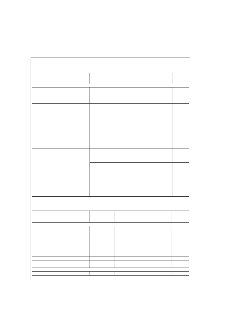
Filter Electrical Characteristics
(Continued)
The following specifications apply for f
≤
250 kHz (Note 3) unless otherwise specified.
Boldface limits apply for T
MIN
to T
MAX
;
all other limits T
A
= T
J
= 25C.
Parameter
Conditions
Typical
Tested
Design
Units
(Note 8)
Limit
Limit
(Note 9)
(Note 10)
V
+
= +2.5V, V
= 2.5V
Total Supply Current
f
CLK
=250 kHz
2.5
4.0
4.0
mA
Maximum
Filter Output
20
mV
Feedthrough
Op Amp 1 Out
15
(peak-to-
Op Amp 2 Out
10
peak)
H
o
, DC Gain
R
source
≤
2 k
0.0
±
0.30
±
0.30
dB
f
CLK
/f
c
, Clock to
Cutoff
MF6-50
49.10
±
0.3%
49.10
±
2%
49.10
±
3%
Ratio
MF6-100
98.65
±
0.3%
98.65
±
2%
98.65
±
2.25%
DC
MF6-50
200
mV
Offset Voltage
MF6-100
400
Minimum Output
R
L
=10 k
+1.5
+1.0
+1.0
V
Voltage Swing
2.2
1.7
1.5
Maximum
Source
28
Short Circuit
Sink
0.5
mA
Current
Dynamic Range (Note 2)
77
dB
Additional
MF6-50
f
CLK
=250 kHz
f=6000 Hz
Magnitude
9.54
9.54
±
0.6
9.54
±
0.75
dB
Response Test
f=4500 Hz
0.96
0.96
±
0.3
0.96
±
0.4
Points (Note
4)
MF6-100
f
CLK
=250 kHz
f=3000 Hz
9.67
9.67
±
0.6
9.67
±
0.75
dB
f=2250 Hz
1.01
1.01
±
0.3
1.01
±
0.4
Attenuation
MF6-50
f
CLK
=250 kHz
f
1
=6000 Hz
f
2
=8000 Hz
f
CLK
=250 kHz
f
1
=3000 Hz
f
2
=4000 Hz
dB/
Rate
36
36
octave
MF6-100
dB/
36
36
octave
Op Amp Electrical Characteristics
Boldface limits apply for T
MIN
to T
MAX
;
all other limits T
A
= T
J
= 25C.
Parameter
Conditions
Typical
(Note 8)
Tested
Limit
(Note 9)
Design
Limit
(Note 10)
Units
V
+
= +5V, V
= 5V
Input Offset Voltage
Input Bias Current
CMRR (Op Amp
#
2 Only)
±
8.0
10
60
±
20
±
20
mV
pA
dB
V
CM1
= 1.8V,
V
CM2
= 2.2V
R
L
=10 k
55
Output Voltage Swing
+4.0
4.5
54
2.0
7.0
72
1.2
+3.8
4.0
65
4.0
+3.6
4.0
80
6.0
V
Maximum Output Short
Circuit Current (Note 6)
Slew Rate
DC Open Loop Gain
Gain Bandwidth Product
V
+
= +2.5V, V
= 2.5V
Input Offset Voltage
Source
Sink
mA
V/μs
dB
MHz
±
8.0
±
20
±
20
mV
www.national.com
3
相關(guān)PDF資料 |
PDF描述 |
|---|---|
| MFE1842BBU22 | Dielectric Filter with Attenuation Pole |
| MG-12232-3 | LCD MODULE |
| MG-12232-5 | LCD MODULE |
| MG25J6ES40 | HIGH POWER SWITCHING APPLICATIONS MOTOR CONTROL APPLICATIONS. |
| MGM3000X | Video Modulator for FM/AM-Audio |
相關(guān)代理商/技術(shù)參數(shù) |
參數(shù)描述 |
|---|---|
| MF6. 3FD101MD13TP | 制造商:nippon chemicon 功能描述: |
| MF6.3FC101MD13TP | 制造商:UCC 功能描述: 制造商:United Chemi-Con Inc 功能描述: |
| MF6.3FC22RMD6TP | 制造商:United Chemi-Con Inc 功能描述: |
| MF60 | 制造商:RIEDON 制造商全稱:Riedon Powertron 功能描述:Film Resistors |
| MF6000-04 | 制造商:KAYNAR (ALCOA) 功能描述: |
發(fā)布緊急采購,3分鐘左右您將得到回復。