- 您現(xiàn)在的位置:買賣IC網(wǎng) > PDF目錄1954 > MCZ33793EF (Freescale Semiconductor)IC DSI SLAVE REMOTE SENS 16-SOIC PDF資料下載
參數(shù)資料
| 型號(hào): | MCZ33793EF |
| 廠商: | Freescale Semiconductor |
| 文件頁數(shù): | 16/27頁 |
| 文件大?。?/td> | 0K |
| 描述: | IC DSI SLAVE REMOTE SENS 16-SOIC |
| 標(biāo)準(zhǔn)包裝: | 48 |
| 類型: | 傳感器接口 |
| 輸入類型: | 邏輯 |
| 輸出類型: | 邏輯 |
| 接口: | 并聯(lián) |
| 電流 - 電源: | 250mA |
| 安裝類型: | 表面貼裝 |
| 封裝/外殼: | 16-SOIC(0.154",3.90mm 寬) |
| 供應(yīng)商設(shè)備封裝: | 16-SOIC N |
| 包裝: | 管件 |
| 產(chǎn)品目錄頁面: | 808 (CN2011-ZH PDF) |
第1頁第2頁第3頁第4頁第5頁第6頁第7頁第8頁第9頁第10頁第11頁第12頁第13頁第14頁第15頁當(dāng)前第16頁第17頁第18頁第19頁第20頁第21頁第22頁第23頁第24頁第25頁第26頁第27頁
Analog Integrated Circuit Device Data
Freescale Semiconductor
23
33793
TYPICAL APPLICATIONS
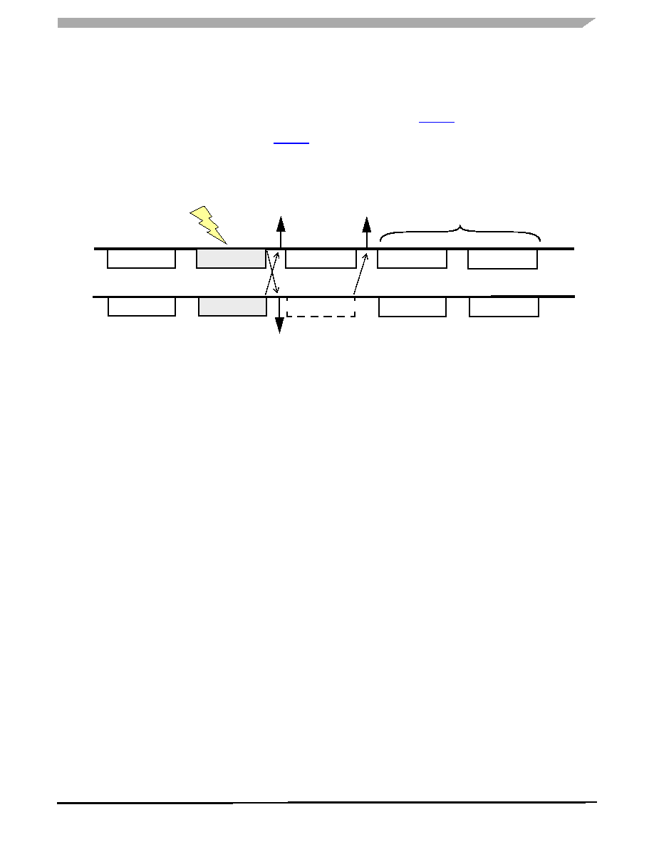
If there is a bus error (due to induced noise or a bus fault),
both the master and slave devices will read bad data. The
slave reacts to bad data by not sending a response during the
next frame. The master will detect a CRC error once it
receives the corrupted data sent by the slave, and once again
when the slave fails to respond. This is illustrated in Figure 7.
When this error occurs, the system software needs to
acknowledge this condition and resend a command (any
command of same size) so that it can receive the previous
response just prior to the bus fault condition (in this case,
Command N).
Failure to take corrective action will result in unintended
errors as shown in Figure 7. In this case, the master will miss
Responses N+1 and N+2 and will mistake them for N+3 and
N+4. The master should send another N+1 command after
the error is acknowledged to re-synchronize the command-
response sequence.
Figure 7. Bus Traffic With Receive Errors (Master Reads Incorrect Data)
POWER UP RESET
When power is first applied to the DSI bus, the system must
allow enough time for the internal 5.0 volt regulator of each
device to come up to a proper level. This implies that H_CAP
must charge up to VRECT + 5.0 V, or approximately 6.0 volts.
The time this takes is a function of the size of H_CAP, and the
current drive of the Master. The following equation can be
used to estimate the minimum time to wait before sending an
Initialization Command:
tMIN (H_CAP x 6V) / ICHARGE
where ICHARGE is the charging current provided by the DSI
Master.
The above assumes a daisy-chain type of bus topology, and
enough time must be allowed for all down-stream devices in
the chain to charge up. For example, if device #1 has it’s
switch closed after its Initialization Command, then the
system must wait for device #2 to power up before sending
its Initialization Command, and so on down the line.
If the devices are attached in a parallel or point-to-point bus
configuration, then the total capacitor value is the sum of all
H_CAPS.
In addition to the charge up time, enough time must be
allocated for the bus fault test (see next section).
BUS FAULTS
A bus fault is defined as an external voltage on the “Inactive
Side” of the Bus Switch that is greater than 3V (typical).
Inactive refers to the side of the bus that is not yet connected
to the bus. Just before a device is Forward Initialized, the
inactive side is defined as BUSOUT. Similarly, just before a
device is Reverse Initialized, the BUSIN is defined as the
inactive side.
The test for a bus fault is only performed once during Forward
or Reverse Initialization (when BS bit is set) by applying an
11 mA pull-down current to the inactive side of the Bus
Switch and monitoring the voltage. The fault test takes
approximately 200
S. If no fault is detected, the bus switch
will be closed, and if a fault is detected, the bus switch will not
close. The fault test applies to both programmed and
unprogrammed devices.
Exception: In the case of a daisy-chain bus topology where
the last device BUSOUT line connects to BUSIN of the first
device (loop-back), then the fault test will NOT be executed
since both BUSIN and BUSOUT are connected to active
busses. It is up to the system software to run the appropriate
diagnostic tests to resolve this special case. (One alternative
is to use a separate DSI Master to handle the loop-back
signal path. This second DSI Master is only activated in the
case of a bus fault so that the last device can be accessed by
means of a reverse initialization.)
GLOBAL ADDRESS 0
Any time an Initialization or Reverse Initialization command is
sent to the 33793 with an address of 0x0 (global address), the
device behaves as follows:
Device initializes to address 0.
Bus switch remains open. This implies that in a daisy-
chain bus topology, all devices past the first device will
remain off.
NV and BS bits are not stored and have no effect.
Command N
Bus Error
Command N+1
Command N+2
Response N-1
Response N
No Response
Response N
Command N+3
Command N+4
Response N+3
CRC
Error
CRC
Error
CRC
Master
Slave
Data misinterpreted by Master
相關(guān)PDF資料 |
PDF描述 |
|---|---|
| MCZ33797EKR2 | IC SQUIB DRIVER 2CHAN 32-SOIC |
| MCZ33884EG | IC MULTIPLE CONTACT MON 24-SOIC |
| MCZ33905BD3EK | IC SBC CAN HS 3.3V 54SOIC |
| MCZ33972EWR2 | IC SWITCH DETECTION MULT 32-SOIC |
| MCZ33975AEKR2 | IC SWITCH DETECT MULT ENH 32SOIC |
相關(guān)代理商/技術(shù)參數(shù) |
參數(shù)描述 |
|---|---|
| MCZ33793EFR2 | 功能描述:輸入/輸出控制器接口集成電路 ORION RoHS:否 制造商:Silicon Labs 產(chǎn)品: 輸入/輸出端數(shù)量: 工作電源電壓: 最大工作溫度:+ 85 C 最小工作溫度:- 40 C 安裝風(fēng)格:SMD/SMT 封裝 / 箱體:QFN-64 封裝:Tray |
| MCZ33797EK | 功能描述:功率驅(qū)動(dòng)器IC FOUR CHANNEL SQUIB DR RoHS:否 制造商:Micrel 產(chǎn)品:MOSFET Gate Drivers 類型:Low Cost High or Low Side MOSFET Driver 上升時(shí)間: 下降時(shí)間: 電源電壓-最大:30 V 電源電壓-最小:2.75 V 電源電流: 最大功率耗散: 最大工作溫度:+ 85 C 安裝風(fēng)格:SMD/SMT 封裝 / 箱體:SOIC-8 封裝:Tube |
| MCZ33797EKR2 | 功能描述:功率驅(qū)動(dòng)器IC FOUR CHANNEL SQUIB DR RoHS:否 制造商:Micrel 產(chǎn)品:MOSFET Gate Drivers 類型:Low Cost High or Low Side MOSFET Driver 上升時(shí)間: 下降時(shí)間: 電源電壓-最大:30 V 電源電壓-最小:2.75 V 電源電流: 最大功率耗散: 最大工作溫度:+ 85 C 安裝風(fēng)格:SMD/SMT 封裝 / 箱體:SOIC-8 封裝:Tube |
| MCZ33800EK | 功能描述:馬達(dá)/運(yùn)動(dòng)/點(diǎn)火控制器和驅(qū)動(dòng)器 AUTO ENG Control IC RoHS:否 制造商:STMicroelectronics 產(chǎn)品:Stepper Motor Controllers / Drivers 類型:2 Phase Stepper Motor Driver 工作電源電壓:8 V to 45 V 電源電流:0.5 mA 工作溫度:- 25 C to + 125 C 安裝風(fēng)格:SMD/SMT 封裝 / 箱體:HTSSOP-28 封裝:Tube |
| MCZ33800EKR2 | 功能描述:馬達(dá)/運(yùn)動(dòng)/點(diǎn)火控制器和驅(qū)動(dòng)器 AUTO ENG CONTROL IC RoHS:否 制造商:STMicroelectronics 產(chǎn)品:Stepper Motor Controllers / Drivers 類型:2 Phase Stepper Motor Driver 工作電源電壓:8 V to 45 V 電源電流:0.5 mA 工作溫度:- 25 C to + 125 C 安裝風(fēng)格:SMD/SMT 封裝 / 箱體:HTSSOP-28 封裝:Tube |
發(fā)布緊急采購,3分鐘左右您將得到回復(fù)。