- 您現(xiàn)在的位置:買賣IC網(wǎng) > PDF目錄382301 > MC33121 (Motorola, Inc.) LOW VOLTAGE SUBSCRIBER LOOP INTERFACE CIRCUIT PDF資料下載
參數(shù)資料
| 型號: | MC33121 |
| 廠商: | Motorola, Inc. |
| 英文描述: | LOW VOLTAGE SUBSCRIBER LOOP INTERFACE CIRCUIT |
| 中文描述: | 低電壓用戶環(huán)路接口電路 |
| 文件頁數(shù): | 20/32頁 |
| 文件大小: | 570K |
| 代理商: | MC33121 |
第1頁第2頁第3頁第4頁第5頁第6頁第7頁第8頁第9頁第10頁第11頁第12頁第13頁第14頁第15頁第16頁第17頁第18頁第19頁當前第20頁第21頁第22頁第23頁第24頁第25頁第26頁第27頁第28頁第29頁第30頁第31頁第32頁

MC33121
20
MOTOROLA
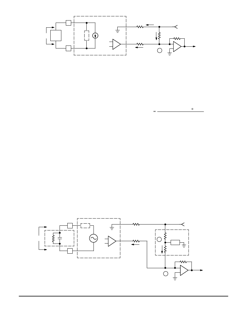
Figure 36. Balance Resistor
–
+
–
+
A
TIP
RING
MC33121
VTX
RXI
TXO
IRX
RB
VL
RRX
IB
VRX
ITX1
ZL
RTX1
RTX2
Zac
–102 IRX
VL x 0.328
Equation 17 provides a value for an RB resistor which will
provide the correct magnitude for IB. The correct phase rela-
tionship is provided by the fact that the signal at TXO is out of
phase with that at VRX. The phase relationship will be 180
°
only
if RRO and RRX are of a configuration identical to that
of the load. This applies regardless of whether the load, ZL,
(and RRO and RRX) are purely resistive or of a complex
nature. Equation 17 reduces to a non–complex resistance if
RRX, Zac, and ZL are all comparably complex.
For the case where Zac = ZL, RRX = 51
Zac, and RC =
1.0 k, Equation 17 reduces to:
RB = 3.15
RTX1
(18)
b) For the case where Zac and ZL do not have the same
frequency characteristics:
For the case where, for reasons of cost and/or simplicity,
the load (RL) is considered resistive (whereas in reality it is
not a pure resistance) and therefore resistors, rather than
networks, were selected for RRO and RRX, using a simple
resistor for RB may not provide sufficient transhybrid rejec-
tion due to a phase angle difference between VRX and TXO.
The terminating impedance may therefore not necessarily be
matched exactly to the line impedance, but the resulting cir-
cuit still provides sufficiently correct performance for receive
gain, transmit gain, and return loss. The rejection can be im-
proved in this case by replacing RB with the configuration
shown in Figure 37. Even on a very short phone line there is
a reactive component to the load due to the two compensa-
tion capacitors (CC, Figure 4) at the transistor collectors. The
two capacitors can be considered in series with each other,
and across the load as shown in Figure 37. To simplify the
explanation, the current source and Zac of Figure 36 are
replaced with the Thevenin voltage source and series Zac.
Since ZL and Zac are not matched, there will be a phase shift
from VRX to the signal across Tip and Ring. This phase shift
is also present at TXO. The same phase shift is generated at
node B in the RB network by making RB1 equal to Zac, and
ZL equal to the load. RB2 is then calculated from:
RRX
RTX1
(RC
33.5
Zac
31 k
RB2
31 k)
(19)
For example, for a system where the load is considered a
600
resistor (RRO = 20.3 k
, RRX = 30.6 k
, RTX1 =
10 k
, and RC = 1.0 k
), RB1 would be a 600
resistor, ZL
(in the RB network) would be a 600
resistor in parallel with
a 0.005
μ
F capacitor, and RB2 calculates to 15.715 k
.
The RB resistor, or network, must have a tolerance equal
to or better than the required system tolerance for trans-
hybrid rejection.
9) Logic Interface
The logic circuit (output ST1, and the I/O labeled ST2/PDI)
is depicted in Figure 30, and functions according to the
Status Output Truth Table (Table 1).
a) Output Characteristics
ST1 is a traditional NPN pull–down with a 15 k
pull–up
resistor. Figures 19 and 20 indicate its output characteristics.
ST2 is configured with the following items: a) a 1.0 mA cur-
rent source for a pull–down which is active only when ST2 is
internally set low; b) an 800
μ
A current source pull–up which
is active only when ST2 is internally set high; c) a positive
Figure 37. Balance Network
–
+
–
+
A
B
TIP
RING
MC33121
VTX
RXI
TXO
RB
VL
RRX
IB
VRX
ITX1
ZL
RTX1
RTX2
Zac
0.005
μ
F
VS
Rac
ZL
RB1
RB2
相關(guān)PDF資料 |
PDF描述 |
|---|---|
| MC33121FN | LOW VOLTAGE SUBSCRIBER LOOP INTERFACE CIRCUIT |
| MC33121P | LOW VOLTAGE SUBSCRIBER LOOP INTERFACE CIRCUIT |
| MC33151 | High Speed Dual MOSFET Drivers |
| MC33151DR2 | High Speed Dual MOSFET Drivers |
| MC34151DR2 | High Speed Dual MOSFET Drivers |
相關(guān)代理商/技術(shù)參數(shù) |
參數(shù)描述 |
|---|---|
| MC33121FN | 制造商:Motorola Inc 功能描述: |
| MC33121P | 制造商:Rochester Electronics LLC 功能描述:SLIC III - Bulk |
| MC33128 | 制造商:MOTOROLA 制造商全稱:Motorola, Inc 功能描述:POWER MANAGEMENT CONTROLLER |
| MC33128D | 制造商:MOTOROLA 制造商全稱:Motorola, Inc 功能描述:POWER MANAGEMENT CONTROLLER |
| MC33129 | 制造商:FREESCALE 制造商全稱:Freescale Semiconductor, Inc 功能描述:High Performance Current Mode Controllers |
發(fā)布緊急采購,3分鐘左右您將得到回復。