- 您現(xiàn)在的位置:買賣IC網(wǎng) > PDF目錄382301 > MC33121 (Motorola, Inc.) LOW VOLTAGE SUBSCRIBER LOOP INTERFACE CIRCUIT PDF資料下載
參數(shù)資料
| 型號: | MC33121 |
| 廠商: | Motorola, Inc. |
| 英文描述: | LOW VOLTAGE SUBSCRIBER LOOP INTERFACE CIRCUIT |
| 中文描述: | 低電壓用戶環(huán)路接口電路 |
| 文件頁數(shù): | 18/32頁 |
| 文件大小: | 570K |
| 代理商: | MC33121 |
第1頁第2頁第3頁第4頁第5頁第6頁第7頁第8頁第9頁第10頁第11頁第12頁第13頁第14頁第15頁第16頁第17頁當(dāng)前第18頁第19頁第20頁第21頁第22頁第23頁第24頁第25頁第26頁第27頁第28頁第29頁第30頁第31頁第32頁

MC33121
18
MOTOROLA
Zac is the impedance looking into the circuit from Tip and
Ring (set by RRO), and is defined as VL/IL. Half of Zac is
from Tip to VCC, and the other half is from Ring to VQB (an
AC ground). Each half is made up of a synthesized imped-
ance (ZT/2) in parallel with RS and (RC + 31 k). Therefore,
Zac is equal to:
Zac = [ZT/2//RS//(RC + 31 k)]
2
ZT
2
{RS
The synthesized impedance ZT is created as follows:
An incoming signal VL produces a differential voltage at
CP and CN, and therefore at TXO equal to:
(5)
{RS
(RC
(RC
31 k)}
(Zac2)
31 k)} – (Zac2)
(6)
and
VTXO
VL
31 k
0.328
(RC
31 k)
(7)
The signal at TXO creates an AC current IRXI through
RRO. RXI is a virtual ground, and CRO is insignificant for first
order calculations.
IRXI is gained up by a factor of 102 to produce the current
IT through the transistors.
ZT is therefore VL/IT. The relationship between ZT and
RRO is:
ZT
1.037
106
(31 k
RRO
RC)
(8)
While equation 8 gives the exact value for RRO, a first order
approximation is Zac
33.5.
a) Resistive Loads (with RC = 1.0 k, RS = 9.1 k):
For a 600
resistive system, ZT calculates to 626
, and
RRO calculates to 20.3 k
.
For a 900
resistive system, ZT calculates to 961
, and
RRO calculates to 31.14 k
.
b) Complex Loads
For complex (nonresistive) loads, the MC33121 must be
made to look like a termination impedance equal to that com-
plex load. This is accomplished by configuring RRO the
same as the complex load, but with all impedance values
increased according to the scaling factor of Equation 9.
SF
[(RC
31 k)
[(RC
31 k)
RS]
1.037
106
31 k)
(RC
RS– (Zac2)]
(9)
Zac is computed at a nominal frequency of interest. A first
order approximation of Equation 9 is:
SF = 1.037
106/(RC + 31 k)
(9a)
For example:
IF THE AC LOAD IS:
THEN RRO SHOULD BE:
TO
RXI
900
TO TIP
AND RING
FROM
TXO
31.15 k (RRO)
62 nF (CRO)
820
0.115
μ
F
CRO
3.3 nF
28.4 k
7.61 k
IF THE AC LOAD IS:
THEN RRO SHOULD BE:
TO
RXI
TO TIP
AND RING
FROM
TXO
220
2.16
μ
F
CRO must remain in series with the network to provide DC
blocking. If the load network does not include a series capac-
itor (as in the second example above), CRO should be large
(1.0
μ
F) so its impedance does not affect the RRO network.
The above procedure will yield a return loss measurement
which is constant with respect to frequency. The RRO resis-
tor, or network, must have a tolerance equal to or better than
the required system tolerance for return loss and receive
gain.
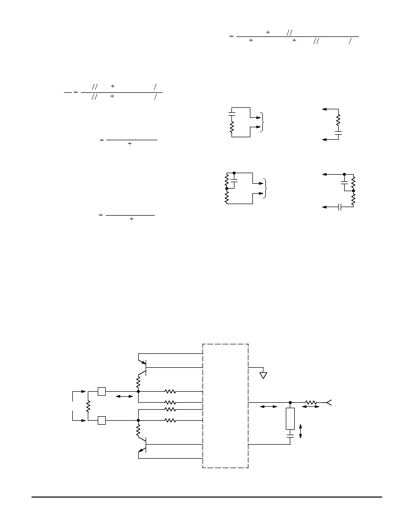
6) Receive Gain (GRX)
The receive gain involves the same circuit as Figure 34,
but with the addition of the RRX resistor (or network) which
sets the receive gain. See Figure 35.
Figure 35. Receive Gain
TIP
RING
EP
BP
RSI
CN
BN
EN
IL
MC33121
TSI
CP
RAC
RP
100
RC 1.0 k
RS 9.1 k
VAG
RXI
TXO
IRXI
RRO
CRO
RP
100
RC 1.0 k
RS 9.1 k
VL
RRX
IR
VRX
ITXO
相關(guān)PDF資料 |
PDF描述 |
|---|---|
| MC33121FN | LOW VOLTAGE SUBSCRIBER LOOP INTERFACE CIRCUIT |
| MC33121P | LOW VOLTAGE SUBSCRIBER LOOP INTERFACE CIRCUIT |
| MC33151 | High Speed Dual MOSFET Drivers |
| MC33151DR2 | High Speed Dual MOSFET Drivers |
| MC34151DR2 | High Speed Dual MOSFET Drivers |
相關(guān)代理商/技術(shù)參數(shù) |
參數(shù)描述 |
|---|---|
| MC33121FN | 制造商:Motorola Inc 功能描述: |
| MC33121P | 制造商:Rochester Electronics LLC 功能描述:SLIC III - Bulk |
| MC33128 | 制造商:MOTOROLA 制造商全稱:Motorola, Inc 功能描述:POWER MANAGEMENT CONTROLLER |
| MC33128D | 制造商:MOTOROLA 制造商全稱:Motorola, Inc 功能描述:POWER MANAGEMENT CONTROLLER |
| MC33129 | 制造商:FREESCALE 制造商全稱:Freescale Semiconductor, Inc 功能描述:High Performance Current Mode Controllers |
發(fā)布緊急采購,3分鐘左右您將得到回復(fù)。