- 您現(xiàn)在的位置:買賣IC網(wǎng) > PDF目錄383513 > MAX8729EEI (MAXIM INTEGRATED PRODUCTS INC) Constant-Frequency, Half-Bridge CCFL Inverter Controller PDF資料下載
參數(shù)資料
| 型號: | MAX8729EEI |
| 廠商: | MAXIM INTEGRATED PRODUCTS INC |
| 元件分類: | 模擬信號調(diào)理 |
| 英文描述: | Constant-Frequency, Half-Bridge CCFL Inverter Controller |
| 中文描述: | SPECIALTY ANALOG CIRCUIT, PDSO28 |
| 封裝: | 0.150 INCH, 0.025 INCH PITCH, MO-137AF, QSOP-28 |
| 文件頁數(shù): | 16/26頁 |
| 文件大小: | 395K |
| 代理商: | MAX8729EEI |
第1頁第2頁第3頁第4頁第5頁第6頁第7頁第8頁第9頁第10頁第11頁第12頁第13頁第14頁第15頁當(dāng)前第16頁第17頁第18頁第19頁第20頁第21頁第22頁第23頁第24頁第25頁第26頁
M
Constant-Frequency, Half-Bridge CCFL
Inverter Controller
16
______________________________________________________________________________________
continues below ground to start the negative cycle.
During the negative half cycle, the controller turns off
the low-side switch at t
4
. After which, the controller
turns on the high-side switch under ZVS conditions and
a new cycle begins. In both cases, A and B, ZVS oper-
ation reduces the turn-on switching losses of both
power switches, resulting in better efficiency.
Resonant Startup
The MAX8729 operates in resonant mode during start-
up. In resonant operation, the inverter keeps increasing
the secondary voltage until either the lamp is struck or
the controller activates overvoltage protection. In reso-
nant mode, the switching frequency is synchronized
with the natural resonant frequency of the resonant tank
circuit composed of: transformer leakage inductance,
primary capacitive divider, and secondary resonant
capacitor. The synchronization and phase-shift func-
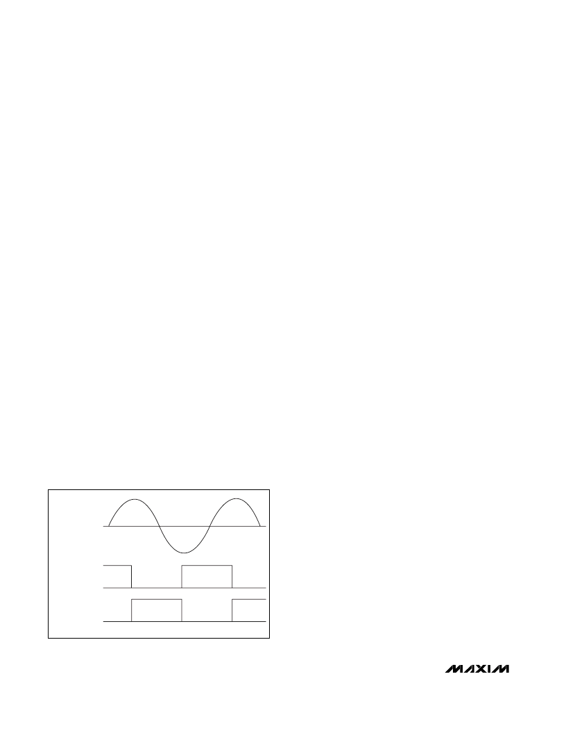
tions are disabled during startup. Figure 4 demon-
strates the resonant operation, with a timing diagram of
the primary current and gate signals. In the resonant
mode, the high side turns on at the beginning of the
positive half cycle. The primary current ramps up. The
controller turns off the high-side switch at t
1
to regulate
the lamp current. The primary current continues to flow
in the same direction, which forward biases the body
diode of the low-side switch after the high-side switch
is off. When the controller turns on the low-side switch,
the voltage drop across the switch is nearly zero. This
ZVS operation results in lower switching losses. With
DL on, the primary current ramps down through zero
until t
2
, when the controller turns off the low-side switch.
After which, the controller turns on the high-side switch
with ZVS condition and a new cycle begins. The ZVS
operation of this architecture reduces the turn-on
switching losses of both power switches, resulting in
better efficiency.
Lamp-Current Regulation
The MAX8729 uses a lamp-current control loop to regu-
late the current delivered to the CCFL. The heart of the
control loop is a transconductance error amplifier in
Figure 2. The AC lamp current is sensed with a sense
resistor connected in series with the low-voltage termi-
nal of the lamp. The voltage across this resistor is fed to
the IFB input and is internally full-wave rectified. The
transconductance error amplifier compares the recti-
fied IFB voltage with a 790mV (typ) internal reference to
generate an error current. The error current charges
and discharges a capacitor connected between the
error amplifier’s output (COMP) and ground to create
an error voltage (V
COMP
). V
COMP
is then compared
with an internal ramp signal to control the high-side
MOSFET switch on-time (t
ON
).
Transformer Secondary Voltage Limiting
The MAX8729 reduces the voltage stress on the trans-
former’s secondary winding by limiting the secondary
voltage during startup and open-lamp fault. The AC
voltage across the transformer secondary winding is
sensed through a capacitive voltage-divider. The volt-
age across the low-side capacitor of the divider is fed
to the VFB input and is internally half-wave rectified. An
overvoltage comparator compares the VFB voltage with
a 2.3V (typ) internal threshold. Once the sense voltage
exceeds the overvoltage threshold, the MAX8729 turns
on a 1.2mA current source that discharges the COMP
capacitor. As the COMP voltage decreases, the high-
side MOSFET’s on-time shortens, which reduces the
transformer secondary peak voltage. The MAX8729
stops discharging the COMP capacitor after the sec-
ondary peak voltage is below the threshold set by the
capacitive voltage-divider. This mechanism effectively
limits the secondary voltage.
Lamp Startup
A CCFL is a gas-discharge lamp that is normally driven
in the avalanche mode. To start ionization in a nonion-
ized lamp, the applied voltage (striking voltage) must
be increased to the level required to start ionization in
the lamp. For example, the normal running voltage of a
typical CCFL is around 650V
RMS
, but the striking volt-
age can be as high as 1800V
RMS
.
The MAX8729’s unique resonant startup method
ensures reliable striking. Before the lamp is ionized, the
lamp impedance is infinite. The transformer secondary
leakage inductance and the high-voltage parallel
capacitor determine the unloaded resonant frequency.
Since the unloaded resonant circuit has a high Q, the
inverter keeps increasing the secondary voltage until
either the lamp is struck or the controller activates the
secondary overvoltage protection.
t
1
t
2
PRIMARY CURRENT
DH
DL
Figure 4. Resonant-Operation Timing Diagram
相關(guān)PDF資料 |
PDF描述 |
|---|---|
| MAX8740 | TFT-LCD Step-Up DC-DC Converter |
| MAX8740ETB | TFT-LCD Step-Up DC-DC Converter |
| MAX878LCPA | Analog IC |
| MAX8710 | LCD display panel power supply TFT Monitor TV |
| MAX8711 | LCD display panel power supply TFT Monitor TV |
相關(guān)代理商/技術(shù)參數(shù) |
參數(shù)描述 |
|---|---|
| MAX8729EEI+ | 功能描述:顯示驅(qū)動器和控制器 Const-f Half-Bridge CCFL Inverter Ctlr RoHS:否 制造商:Panasonic Electronic Components 工作電源電壓:2.7 V to 5.5 V 最大工作溫度: 安裝風(fēng)格:SMD/SMT 封裝 / 箱體:QFN-44 封裝:Reel |
| MAX8729EEI+T | 功能描述:顯示驅(qū)動器和控制器 Const-f Half-Bridge CCFL Inverter Ctlr RoHS:否 制造商:Panasonic Electronic Components 工作電源電壓:2.7 V to 5.5 V 最大工作溫度: 安裝風(fēng)格:SMD/SMT 封裝 / 箱體:QFN-44 封裝:Reel |
| MAX8729EEI-T | 功能描述:顯示驅(qū)動器和控制器 RoHS:否 制造商:Panasonic Electronic Components 工作電源電壓:2.7 V to 5.5 V 最大工作溫度: 安裝風(fēng)格:SMD/SMT 封裝 / 箱體:QFN-44 封裝:Reel |
| MAX8729EVKIT | 功能描述:電源管理IC開發(fā)工具 MAX8729 Eval Kit RoHS:否 制造商:Maxim Integrated 產(chǎn)品:Evaluation Kits 類型:Battery Management 工具用于評估:MAX17710GB 輸入電壓: 輸出電壓:1.8 V |
| MAX872C/D | 功能描述:基準電壓& 基準電流 RoHS:否 制造商:STMicroelectronics 產(chǎn)品:Voltage References 拓撲結(jié)構(gòu):Shunt References 參考類型:Programmable 輸出電壓:1.24 V to 18 V 初始準確度:0.25 % 平均溫度系數(shù)(典型值):100 PPM / C 串聯(lián) VREF - 輸入電壓(最大值): 串聯(lián) VREF - 輸入電壓(最小值): 分流電流(最大值):60 mA 最大工作溫度:+ 125 C 封裝 / 箱體:SOT-23-3L 封裝:Reel |
發(fā)布緊急采購,3分鐘左右您將得到回復(fù)。