- 您現(xiàn)在的位置:買賣IC網(wǎng) > PDF目錄383512 > MAX8722EEG (MAXIM INTEGRATED PRODUCTS INC) Low-Cost CCFL Backlight Controller PDF資料下載
參數(shù)資料
| 型號: | MAX8722EEG |
| 廠商: | MAXIM INTEGRATED PRODUCTS INC |
| 元件分類: | 穩(wěn)壓器 |
| 英文描述: | Low-Cost CCFL Backlight Controller |
| 中文描述: | FLUORESCENT LIGHT CONTROLLER, PDSO24 |
| 封裝: | 0.150 INCH, 0.250 INCH PITCH, MO-137AE, QSOP-24 |
| 文件頁數(shù): | 2/20頁 |
| 文件大小: | 331K |
| 代理商: | MAX8722EEG |

M
Low-Cost CCFL Bac klight Controller
2
_______________________________________________________________________________________
ABSOLUTE MAXIMUM RATINGS
BATT to GND..........................................................-0.3V to +30V
BST1, BST2 to GND ...............................................-0.3V to +36V
BST1 to LX1, BST2 to LX2........................................-0.3V to +6V
CNTL, FREQ, SYNC, V
CC
, V
DD
to GND...................-0.3V to +6V
COMP, DPWM, ILIM, TFLT to GND............-0.3V to (V
CC
+ 0.3V)
GH1 to LX1..............................................-0.3V to (V
BST1
+ 0.3V)
GH2 to LX2..............................................-0.3V to (V
BST2
+ 0.3V)
GL1, GL2 to GND.......................................-0.3V to (V
DD
+ 0.3V)
IFB, ISEC, VFB to GND................................................-3V to +6V
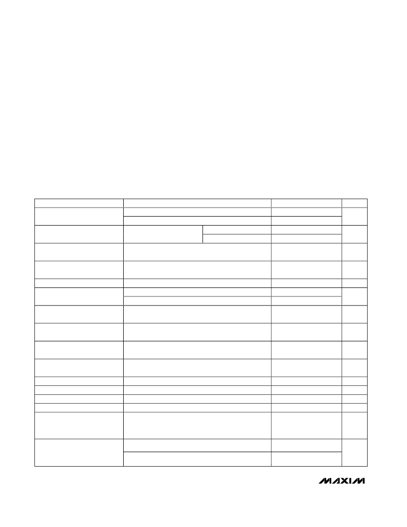
ELECTRICAL CHARACTERISTICS
(Circuit of Figure 1. V
BATT
= 12V, V
CC
= V
DD
, V
SHDN
= 5.3V,
T
A
= 0°C to +85°C
.
Typical values are at T
A
= +25°C, unless otherwise noted.)
Stresses beyond those listed under “Absolute Maximum Ratings” may cause permanent damage to the device. These are stress ratings only, and functional
operation of the device at these or any other conditions beyond those indicated in the operational sections of the specifications is not implied. Exposure to
absolute maximum rating conditions for extended periods may affect device reliability.
SHDN
to GND...........................................................-0.3V to +6V
PGND to GND .......................................................-0.3V to +0.3V
Continuous Power Dissipation (T
A
= +70
°
C)
24-Pin QSOP (derate 9.5mW/
°
C above +70
°
C)........761.9mW
Operating Temperature Range ...........................-40
°
C to +85
°
C
J unction Temperature......................................................+150
°
C
Storage Temperature Range.............................-65
°
C to +150
°
C
Lead Temperature (soldering, 10s) .................................+300
°
C
PARAMETER
CONDITIONS
MIN
4.6
5.5
TYP
MAX
5.5
28.0
2
2
UNITS
V
CC
= V
DD
= V
BATT
V
CC
= V
DD
= open
BATT Input Voltage Range
V
V
BATT
= 28V
V
BATT
= V
CC
= 5V
1
BATT Quiescent Current
V
SHDN
= V
CC
,
V
IFB
= 1V
mA
BATT Quiescent Current,
Shutdown
SHDN
= GND
6
20
μA
V
CC
Output Voltage, Normal
Operation
V
SHDN
= 5.5V, 6V < V
BATT
< 28V,
0 < I
LOAD
< 10mA
SHDN
= GND, no load
V
CC
rising (leaving lockout)
V
CC
falling (entering lockout)
5.25
5.40
5.55
V
V
CC
Output Voltage, Shutdown
3.5
4.6
5.5
4.58
V
V
CC
Undervoltage-Lockout
Threshold
4.0
V
V
CC
Undervoltage-Lockout
Hysteresis
200
mV
GH1, GH2, GL1, GL2 On-
Resistance, High
I
TEST
= 10mA, V
CC
= V
DD
= 5.3V
20
37
GH1, GH2, GL1, GL2 On-
Resistance, Low
I
TEST
= 10mA, V
CC
= V
DD
= 5.3V
10
20
GH1, GH2, GL1, GL2 Maximum
Output Current
0.3
A
BST1, BST2 Leakage Current
Resonant Frequency Range
Minimum Off-Time
Maximum Off-Time
V
BST
_ = 12V, V
LX
_ = 7V
Guaranteed by design
5
μA
kHz
ns
μs
30
340
24
80
600
43
470
33
Current-Limit Threshold
LX1 to PGND, LX2 to PGND
(Fixed)
ILIM = V
CC
180
200
220
mV
V
ILIM
= 0.5V
80
100
120
Current-Limit Threshold
LX1 to PGND, LX2 to PGND
(Adjustable)
V
ILIM
= 2.0V
370
400
430
mV
相關(guān)PDF資料 |
PDF描述 |
|---|---|
| MAX8726EUE | Triple-Output TFT-LCD DC-DC Converters |
| MAX8729 | Constant-Frequency, Half-Bridge CCFL Inverter Controller |
| MAX8729EEI | Constant-Frequency, Half-Bridge CCFL Inverter Controller |
| MAX8740 | TFT-LCD Step-Up DC-DC Converter |
| MAX8740ETB | TFT-LCD Step-Up DC-DC Converter |
相關(guān)代理商/技術(shù)參數(shù) |
參數(shù)描述 |
|---|---|
| MAX8722EEG+ | 功能描述:顯示驅(qū)動器和控制器 CCFL Backlight Controller RoHS:否 制造商:Panasonic Electronic Components 工作電源電壓:2.7 V to 5.5 V 最大工作溫度: 安裝風(fēng)格:SMD/SMT 封裝 / 箱體:QFN-44 封裝:Reel |
| MAX8722EEG+T | 功能描述:顯示驅(qū)動器和控制器 CCFL Backlight Controller RoHS:否 制造商:Panasonic Electronic Components 工作電源電壓:2.7 V to 5.5 V 最大工作溫度: 安裝風(fēng)格:SMD/SMT 封裝 / 箱體:QFN-44 封裝:Reel |
| MAX8722EEG-T | 功能描述:顯示驅(qū)動器和控制器 RoHS:否 制造商:Panasonic Electronic Components 工作電源電壓:2.7 V to 5.5 V 最大工作溫度: 安裝風(fēng)格:SMD/SMT 封裝 / 箱體:QFN-44 封裝:Reel |
| MAX8722EVKIT | 功能描述:顯示開發(fā)工具 Low-Cost CCFL Backlight Controller RoHS:否 制造商:4D Systems 產(chǎn)品:4Display Shields 工具用于評估:?OLED-160-G1, ?OLED-160-G2 接口類型:Serial 工作電源電壓:5 V |
| MAX8723ETE+ | 功能描述:顯示驅(qū)動器和控制器 Int-Switch Step-Down Regulator for LCDs RoHS:否 制造商:Panasonic Electronic Components 工作電源電壓:2.7 V to 5.5 V 最大工作溫度: 安裝風(fēng)格:SMD/SMT 封裝 / 箱體:QFN-44 封裝:Reel |
發(fā)布緊急采購,3分鐘左右您將得到回復(fù)。