- 您現(xiàn)在的位置:買(mǎi)賣(mài)IC網(wǎng) > PDF目錄383493 > MAX712-MAX713 (Maxim Integrated Products, Inc.) NiCd/NiMH Battery Fast-Charge Controllers PDF資料下載
參數(shù)資料
| 型號(hào): | MAX712-MAX713 |
| 廠(chǎng)商: | Maxim Integrated Products, Inc. |
| 英文描述: | NiCd/NiMH Battery Fast-Charge Controllers |
| 中文描述: | 鎳鎘/鎳氫電池快速充電控制器 |
| 文件頁(yè)數(shù): | 12/18頁(yè) |
| 文件大?。?/td> | 168K |
| 代理商: | MAX712-MAX713 |
第1頁(yè)第2頁(yè)第3頁(yè)第4頁(yè)第5頁(yè)第6頁(yè)第7頁(yè)第8頁(yè)第9頁(yè)第10頁(yè)第11頁(yè)當(dāng)前第12頁(yè)第13頁(yè)第14頁(yè)第15頁(yè)第16頁(yè)第17頁(yè)第18頁(yè)
M
NiCd/NiMH Battery
Fast-Charge Controllers
12
______________________________________________________________________________________
The voltage loop is stabilized by the output filter
capacitor. A large filter capacitor is required
only
if the
load is going to be supplied by the MAX712/MAX713 in
the absence of a battery. In this case, set C
OUT
as:
C
OUT
(in farads) = (50 x I
LOAD
) / (V
OUT
x BW
VRL
)
where BW
VRL
= loop bandwidth in Hz
(10,000 recommended)
C
OUT
> 10μF
I
LOAD
= external load current in amps
V
OUT
= programmed output voltage
(V
LIMIT
x number of cells)
Current Loop
Figure 6 shows the current-regulation loop for a linear-
mode circuit. To ensure loop stability, make sure that
the bandwidth of the current regulation loop (BW
CRL
) is
lower than the pole frequency of transistor Q1 (f
B
). Set
BW
CRL
by selecting C2.
BW
CRL
in Hz = gm / C2, C2 in farads,
gm = 0.0018 Siemens
The pole frequency of the PNP pass transistor, Q1, can
be determined by assuming a single-pole current gain
response. Both f
T
and B
o
should be specified on the
data sheet for the particular transistor used for Q1.
f
B
in Hz = f
T
/ B
o
, f
T
in Hz, B
o
= DC current gain
Condition for Stability of Current-Regulation Loop:
BW
CRL
< f
B
The MAX712/MAX713 dissipate power due to the cur-
rent-voltage product at DRV. Do not allow the power
dissipation to exceed the specifications shown in the
Absolute Maximum Ratings. DRV power dissipation can
be reduced by using the cascode connection shown in
Figure 5 or by using a switch-mode circuit.
Power dissipation due to DRV sink current =
(current into DRV) x (voltage on DRV)
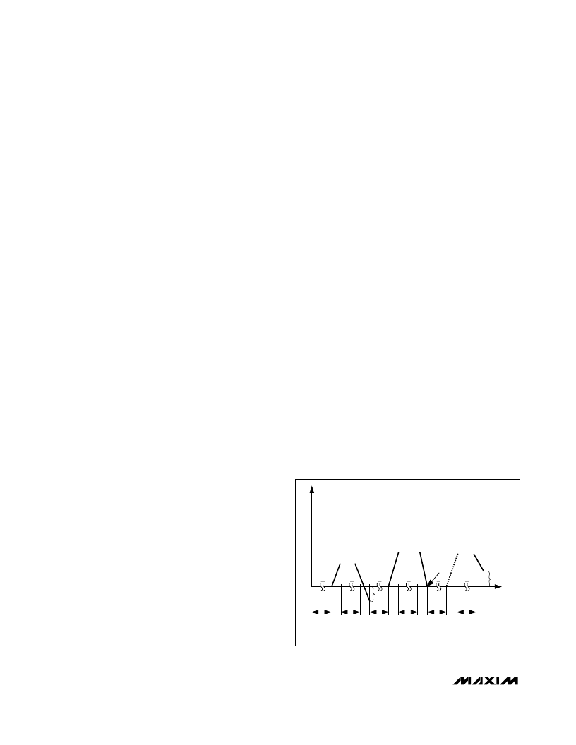
V oltage-S lope Cutoff
The MAX712/MAX713’s internal analog-to-digital con-
verter has 2.5mV of resolution. It determines if the bat-
tery voltage is rising, falling, or unchanging by
comparing the battery’s voltage at two different times.
After power-up, a time interval of t
A
ranging from 21sec
to 168sec passes (see Table 3 and Figure 8), then a
battery voltage measurement is taken. It takes 5ms to
perform a measurement. After the first measurement is
complete, another t
A
interval passes, and then a
second measurement is taken. The two measurements
are compared, and a decision whether to terminate
charge is made. If charge is not terminated, another full
two-measurement cycle is repeated until charge is
terminated. Note that each cycle has two t
A
intervals
and two voltage measurements.
The MAX712 terminates fast charge when a compari-
son shows that the battery voltage is unchanging. The
MAX713 terminates when a conversion shows the bat-
tery voltage has fallen by at least 2.5mV per cell. This is
the only difference between the MAX712 and MAX713.
T emperature Charge Cutoff
Figure 9a shows how the MAX712/MAX713 detect over-
and under-temperature battery conditions using negative
temperature coefficient thermistors. Use the same model
thermistor for T1 and T2 so that both have the same
nominal resistance. The voltage at TEMP is 1V (referred
to BATT-) when the battery is at ambient temperature.
The threshold chosen for THI sets the point at which
fast charging terminates. As soon as the voltage-on
TEMP rises above THI, fast charge ends, and does not
restart after TEMP falls below THI.
The threshold chosen for TLO determines the tem-
perature below which fast charging will be inhibited.
If TLO > TEMP when the MAX712/MAX713 start up, fast
charge will not start until TLO goes below TEMP.
The cold temperature charge inhibition can be disabled
by removing R5, T3, and the 0.022
μ
F capacitor; and by
tying TLO to BATT-.
To disable the entire temperature comparator charge-
cutoff mechanism, remove T1, T2, T3, R3, R4, and R5,
and their associated capacitors, and connect THI to V+
and TLO to BATT-. Also, place a 68kQ resistor from
REF to TEMP, and a 22k
resistor from BATT- to TEMP.
Some battery packs come with a temperature-detecting
thermistor connected to the battery pack’s negative
POSITIVE
RESIDUAL
5ms
5ms
5ms
5ms
5ms
5ms
t
A
t
A
t
A
t
A
t
A
t
A
INTERVAL
NOTE: SLOPE PROPORTIONAL TOVBATT
INTERVAL
INTERVAL
INTERVAL
INTERVAL
INTERVAL
NEGATIVE
RESIDUAL
ZERO
RESIDUAL
VOLTAGE
RISES
0
t
ZERO
VOLTAGE
SLOPE
CUTOFF FOR MAX712
NEGATIVE
VOLTAGE
SLOPE
CUTOFF FOR MAX712
OR MAX713
C
Figure 8. Voltage Slope Detection
相關(guān)PDF資料 |
PDF描述 |
|---|---|
| MAX712EPE | Octal Buffers And Line Drivers With 3-State Outputs 20-CFP -55 to 125 |
| MAX712ESE | Octal Buffers And Line Drivers With 3-State Outputs 20-CDIP -55 to 125 |
| MAX712MJE | Octal Buffers And Line Drivers With 3-State Outputs 20-LCCC -55 to 125 |
| MAX713CPE | NiCd/NiMH Battery Fast-Charge Controllers |
| MAX713CSE | NiCd/NiMH Battery Fast-Charge Controllers |
相關(guān)代理商/技術(shù)參數(shù) |
參數(shù)描述 |
|---|---|
| MAX712MJE | 功能描述:電池管理 NiCd/NiMH Battery Fast-Charge Ctlr RoHS:否 制造商:Texas Instruments 電池類(lèi)型:Li-Ion 輸出電壓:5 V 輸出電流:4.5 A 工作電源電壓:3.9 V to 17 V 最大工作溫度:+ 85 C 最小工作溫度:- 40 C 封裝 / 箱體:VQFN-24 封裝:Reel |
| MAX713 | 制造商:DALLAS 制造商全稱(chēng):Dallas Semiconductor 功能描述:Switch-Mode Battery Charger Delivers 5A |
| MAX713C/D | 制造商:MAXIM 制造商全稱(chēng):Maxim Integrated Products 功能描述:NiCd/NiMH Battery Fast-Charge Controllers |
| MAX713CPE | 功能描述:電池管理 NiCd/NiMH Battery Fast-Charge Ctlr RoHS:否 制造商:Texas Instruments 電池類(lèi)型:Li-Ion 輸出電壓:5 V 輸出電流:4.5 A 工作電源電壓:3.9 V to 17 V 最大工作溫度:+ 85 C 最小工作溫度:- 40 C 封裝 / 箱體:VQFN-24 封裝:Reel |
| MAX713CPE+ | 功能描述:電池管理 NiCd/NiMH Battery Fast-Charge Ctlr RoHS:否 制造商:Texas Instruments 電池類(lèi)型:Li-Ion 輸出電壓:5 V 輸出電流:4.5 A 工作電源電壓:3.9 V to 17 V 最大工作溫度:+ 85 C 最小工作溫度:- 40 C 封裝 / 箱體:VQFN-24 封裝:Reel |
發(fā)布緊急采購(gòu),3分鐘左右您將得到回復(fù)。