- 您現(xiàn)在的位置:買賣IC網(wǎng) > PDF目錄385527 > MAX3774 (Maxim Integrated Products, Inc.) Dual-Rate Fibre Channel Repeaters PDF資料下載
參數(shù)資料
| 型號(hào): | MAX3774 |
| 廠商: | Maxim Integrated Products, Inc. |
| 英文描述: | Dual-Rate Fibre Channel Repeaters |
| 中文描述: | 雙速率的光纖通道中繼器 |
| 文件頁數(shù): | 6/9頁 |
| 文件大?。?/td> | 220K |
| 代理商: | MAX3774 |

M
Detailed Description
Figure 2 shows the functional block diagram of the
MAX3772
–
MAX3775 fibre channel repeaters. They con-
sist of a fully integrated PLL, CML input and output
buffers, and a data latch. The PLL consists of a com-
bined phase detector (PD) and frequency detector
(FD), a loop filter, and a voltage-controlled oscillator
(VCO). The input and output signal buffers employ low-
noise CML architecture and are terminated on-chip.
Phase and Frequency Detector
The frequency difference between the VCO clock and
the received data is derived by sampling the in-phase
and quadrature VCO outputs on the edges of the input
data signal. The FD drives the VCO until the frequency
difference is reduced to zero. Once frequency acquisi-
tion is complete, the PD produces a voltage proportion-
al to the phase difference between the incoming data
and the internal clock. The PLL drives this error voltage
to zero, aligning the recovered clock to the center of
the incoming eye.
Dual-Rate Fibre Channel Repeaters
6
_______________________________________________________________________________________
Pin Description
PIN
NAME
FUNCTION
1
CF+
CDR Filter Capacitor Positive Connection. C
F
= 0.047μF.
2
CF-
CDR Filter Capacitor Negative Connection. C
F
= 0.047μF.
3, 6, 12
GND
Electrical Ground
4
IN+
Noninverted Data Input
5
IN-
Inverted Data Input
7, 8
V
CC
Supply Voltage
9
RATESEL
Rate Select Pin. TTL low selects 1.0625Gbps operation. TTL high selects 2.125Gbps operation.
10
OUT-
Inverted Data Output
11
OUT+
Noninverted Data Output
13
CLKEN
Clock Output Enable. TTL high enables the clock output. TTL low disables the clock output.
14
CLK-
Inverted Clock Output. Enabled when CLKEN is forced high; disabled when CLKEN is forced low.
15
CLK+
Noninverted Clock Output. Enabled when CLKEN is forced high; disabled when CLKEN is forced low.
16
LOCK
Frequency Lock Indicator. When data is present, a high level indicates the PLL is frequency-locked.
The output of the LOCK pin may chatter when large jitter is applied to the input.
EP
Exposed
Paddle
The exposed paddle must be soldered to the circuit board ground for proper thermal performance.
500mVp-p MIN
900mVp-p MAX
1000mVp-p MIN
1800mVp-p MAX
V
OUT
+
V
OUT
-
(V
OUT
+) - (V
OUT
-)
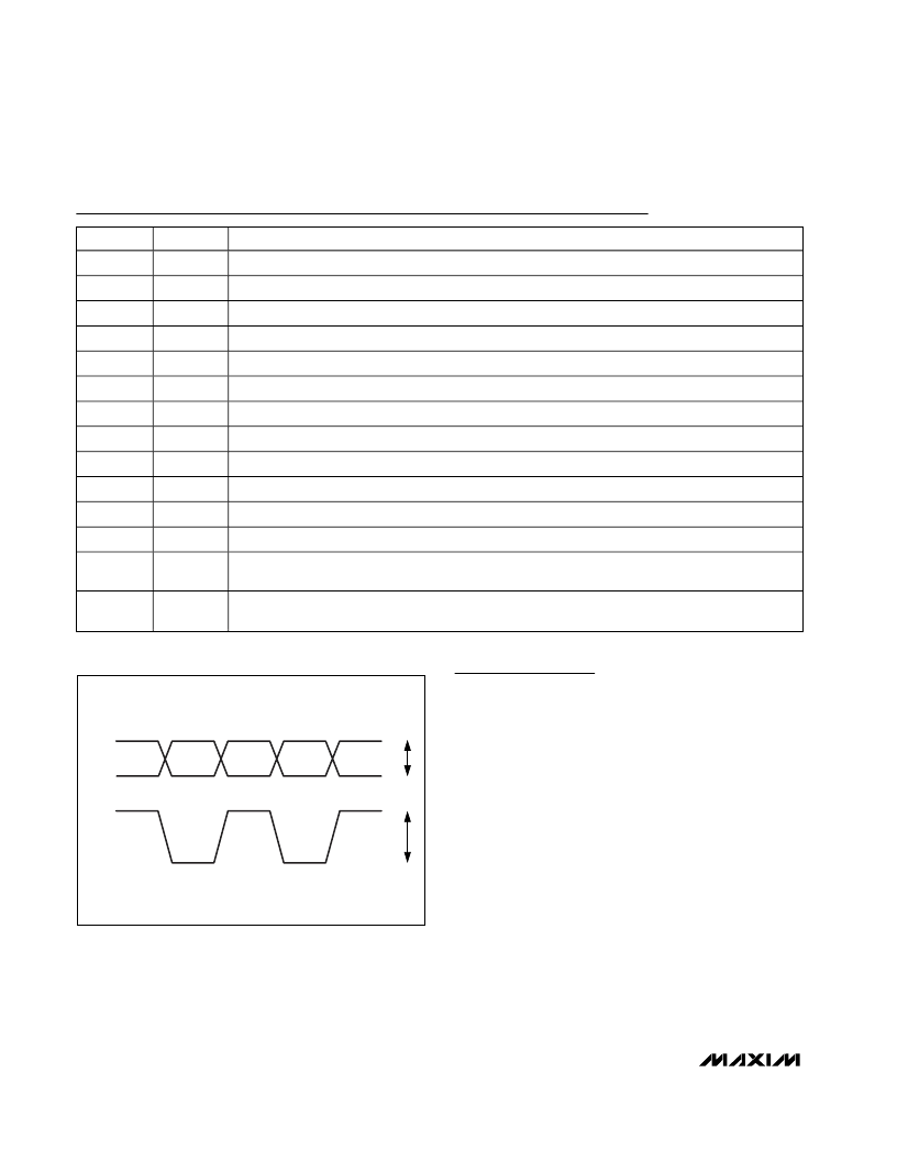
Figure 1. Example of Output Signal with Matched Output Loads
相關(guān)PDF資料 |
PDF描述 |
|---|---|
| MAX3775 | Dual-Rate Fibre Channel Repeaters |
| MAX3772 | Quad LVDS Transmitter with Flow-Through Pinout 16-TSSOP -40 to 85 |
| MAX3772CEE | Replaced by SN65LVDS048A : LVDS Quad Differential Line Receiver 16-SOIC -40 to 85 |
| MAX3773CEE | Replaced by SN65LVDS048A : LVDS Quad Differential Line Receiver 16-TSSOP -40 to 85 |
| MAX3775CEE | Quad LVDS Receiver with Flow-Through Pinout 16-SOIC -40 to 85 |
相關(guān)代理商/技術(shù)參數(shù) |
參數(shù)描述 |
|---|---|
| MAX3774CEE | 制造商:Rochester Electronics LLC 功能描述: 制造商:Maxim Integrated Products 功能描述: |
| MAX3774CEE+T | 制造商:Maxim Integrated Products 功能描述:- Tape and Reel |
| MAX3775CEE+T | 制造商:Maxim Integrated Products 功能描述:- Tape and Reel |
| MAX3780EVKIT | 制造商:Maxim Integrated Products 功能描述:QUAD 2.5GBPS CABLE TRANSCEIVER - Rail/Tube |
| MAX3781EVKIT | 功能描述:交換機(jī) IC 開發(fā)工具 RoHS:否 制造商:Maxim Integrated 產(chǎn)品:Evaluation Kits 類型:USB Power Switches 工具用于評估:MAX4984E 工作電源電壓:2.8 V to 5.5 V |
發(fā)布緊急采購,3分鐘左右您將得到回復(fù)。