- 您現(xiàn)在的位置:買賣IC網(wǎng) > PDF目錄385527 > MAX3774 (Maxim Integrated Products, Inc.) Dual-Rate Fibre Channel Repeaters PDF資料下載
參數(shù)資料
| 型號(hào): | MAX3774 |
| 廠商: | Maxim Integrated Products, Inc. |
| 英文描述: | Dual-Rate Fibre Channel Repeaters |
| 中文描述: | 雙速率的光纖通道中繼器 |
| 文件頁數(shù): | 1/9頁 |
| 文件大?。?/td> | 220K |
| 代理商: | MAX3774 |

General Description
The MAX3772–MAX3775 are dual-rate (1.0625Gbps
and 2.125Gbps) fibre channel repeaters. They are opti-
mized for use in fibre channel arbitrated loop applica-
tions and operate from a +3.3V supply. The
MAX3772–MAX3775 exceed fibre channel jitter toler-
ance requirements and can recover data signals with
up to 0.7 unit interval (UI) jitter. The circuit’s fully inte-
grated phase-locked loop (PLL) provides a frequency
lock indication and does not need an external reference
clock. These repeaters provide low-jitter CML clock and
data outputs, and are pin compatible with the MAX3770
repeater (except RATESEL pin and exposed paddle).
The MAX3773/MAX3774 can also be used for imped-
ance transformation between 100
(differential) and
150
(differential) systems. To reduce the number of
external components, all signal inputs and outputs are
internally terminated. The MAX3772–MAX3775 are
available in 16-pin QSOP-EP packages.
Applications
1.0625Gbps/2.125Gbps Dual-Rate
Fibre Channel
Fibre Channel Data Storage Systems
Storage Area Networks
Fibre Channel Hubs
100
/150
(Differential) Impedance
Transformation
Features
o
Pin Selectable 1.0625Gbps/2.125Gbps Dual-Rate
Fibre Channel Operation
o
Exceeds Fibre Channel Jitter Tolerance
Requirements
o
1400mV Differential Output Swing
o
+3.0V to +3.6V Operation
o
No Reference Clock Required
o
Frequency Lock Indication
o
290mW Power Consumption (MAX3775) at +3.3V
o
100
/150
(differential) Input/Output
Terminations
M
Dual-Rate Fibre Channel Repeaters
________________________________________________________________
Maxim Integrated Products
For pricing, delivery, and ordering information, please contact Maxim/Dallas Direct! at
1-888-629-4642, or visit Maxim’s website at www.maxim-ic.com.
1
Ordering Information
3.3V
Z
o
= 75
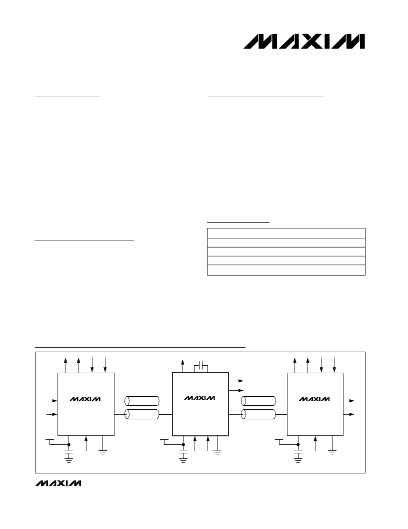
PORT BYPASS CIRCUIT
FIBRE CHANNEL REPEATER
Z
o
= 75
MAX3775
CLK+
CLK-
G
R
C
V
C
0.047
μ
F
0.1
μ
F
OUT+
OUT-
IN+
IN-
C
C
L
3.3V
MAX3750
G
S
V
C
G
S
V
C
0.1
μ
F
OUT+
OUT-
IN+
IN-
L
L
L
L
L
L
L
L
PORT BYPASS CIRCUIT
3.3V
MAX3750
0.1
μ
F
OUT+
OUT-
IN+
IN-
Z
o
= 75
Z
o
= 75
Typical Operating Circuits
19-2192; Rev 0; 10/01
Pin Configuration appears at end of data sheet.
Selector Guide appears at end of data sheet.
PART
TEMP. RANGE
0
°
C to +70
°
C
0
°
C to +70
°
C
0
°
C to +70
°
C
0
°
C to +70
°
C
PIN-PACKAGE
16 QSOP-EP
16 QSOP-EP
16 QSOP-EP
16 QSOP-EP
MAX3772
CEE
MAX3773
CEE
MAX3774
CEE
MAX3775
CEE
相關(guān)PDF資料 |
PDF描述 |
|---|---|
| MAX3775 | Dual-Rate Fibre Channel Repeaters |
| MAX3772 | Quad LVDS Transmitter with Flow-Through Pinout 16-TSSOP -40 to 85 |
| MAX3772CEE | Replaced by SN65LVDS048A : LVDS Quad Differential Line Receiver 16-SOIC -40 to 85 |
| MAX3773CEE | Replaced by SN65LVDS048A : LVDS Quad Differential Line Receiver 16-TSSOP -40 to 85 |
| MAX3775CEE | Quad LVDS Receiver with Flow-Through Pinout 16-SOIC -40 to 85 |
相關(guān)代理商/技術(shù)參數(shù) |
參數(shù)描述 |
|---|---|
| MAX3774CEE | 制造商:Rochester Electronics LLC 功能描述: 制造商:Maxim Integrated Products 功能描述: |
| MAX3774CEE+T | 制造商:Maxim Integrated Products 功能描述:- Tape and Reel |
| MAX3775CEE+T | 制造商:Maxim Integrated Products 功能描述:- Tape and Reel |
| MAX3780EVKIT | 制造商:Maxim Integrated Products 功能描述:QUAD 2.5GBPS CABLE TRANSCEIVER - Rail/Tube |
| MAX3781EVKIT | 功能描述:交換機(jī) IC 開發(fā)工具 RoHS:否 制造商:Maxim Integrated 產(chǎn)品:Evaluation Kits 類型:USB Power Switches 工具用于評(píng)估:MAX4984E 工作電源電壓:2.8 V to 5.5 V |
發(fā)布緊急采購,3分鐘左右您將得到回復(fù)。