- 您現(xiàn)在的位置:買(mǎi)賣(mài)IC網(wǎng) > PDF目錄98006 > M37754S4CGP 16-BIT, 40 MHz, MICROCONTROLLER, PQFP100 PDF資料下載
參數(shù)資料
| 型號(hào): | M37754S4CGP |
| 元件分類(lèi): | 微控制器/微處理器 |
| 英文描述: | 16-BIT, 40 MHz, MICROCONTROLLER, PQFP100 |
| 封裝: | PLASTIC, QFP-100 |
| 文件頁(yè)數(shù): | 78/117頁(yè) |
| 文件大小: | 1575K |
| 代理商: | M37754S4CGP |
第1頁(yè)第2頁(yè)第3頁(yè)第4頁(yè)第5頁(yè)第6頁(yè)第7頁(yè)第8頁(yè)第9頁(yè)第10頁(yè)第11頁(yè)第12頁(yè)第13頁(yè)第14頁(yè)第15頁(yè)第16頁(yè)第17頁(yè)第18頁(yè)第19頁(yè)第20頁(yè)第21頁(yè)第22頁(yè)第23頁(yè)第24頁(yè)第25頁(yè)第26頁(yè)第27頁(yè)第28頁(yè)第29頁(yè)第30頁(yè)第31頁(yè)第32頁(yè)第33頁(yè)第34頁(yè)第35頁(yè)第36頁(yè)第37頁(yè)第38頁(yè)第39頁(yè)第40頁(yè)第41頁(yè)第42頁(yè)第43頁(yè)第44頁(yè)第45頁(yè)第46頁(yè)第47頁(yè)第48頁(yè)第49頁(yè)第50頁(yè)第51頁(yè)第52頁(yè)第53頁(yè)第54頁(yè)第55頁(yè)第56頁(yè)第57頁(yè)第58頁(yè)第59頁(yè)第60頁(yè)第61頁(yè)第62頁(yè)第63頁(yè)第64頁(yè)第65頁(yè)第66頁(yè)第67頁(yè)第68頁(yè)第69頁(yè)第70頁(yè)第71頁(yè)第72頁(yè)第73頁(yè)第74頁(yè)第75頁(yè)第76頁(yè)第77頁(yè)當(dāng)前第78頁(yè)第79頁(yè)第80頁(yè)第81頁(yè)第82頁(yè)第83頁(yè)第84頁(yè)第85頁(yè)第86頁(yè)第87頁(yè)第88頁(yè)第89頁(yè)第90頁(yè)第91頁(yè)第92頁(yè)第93頁(yè)第94頁(yè)第95頁(yè)第96頁(yè)第97頁(yè)第98頁(yè)第99頁(yè)第100頁(yè)第101頁(yè)第102頁(yè)第103頁(yè)第104頁(yè)第105頁(yè)第106頁(yè)第107頁(yè)第108頁(yè)第109頁(yè)第110頁(yè)第111頁(yè)第112頁(yè)第113頁(yè)第114頁(yè)第115頁(yè)第116頁(yè)第117頁(yè)

MITSUBISHI MICROCOMPUTERS
M37754M8C-XXXGP, M37754M8C-XXXHP
M37754S4CGP, M37754S4CHP
SINGLE-CHIP 16-BIT CMOS MICROCOMPUTER
60
PRELIMINAR
Y
Notice:
This
is not
a final
specification.
Some
parametric
limits
are
subject
to change.
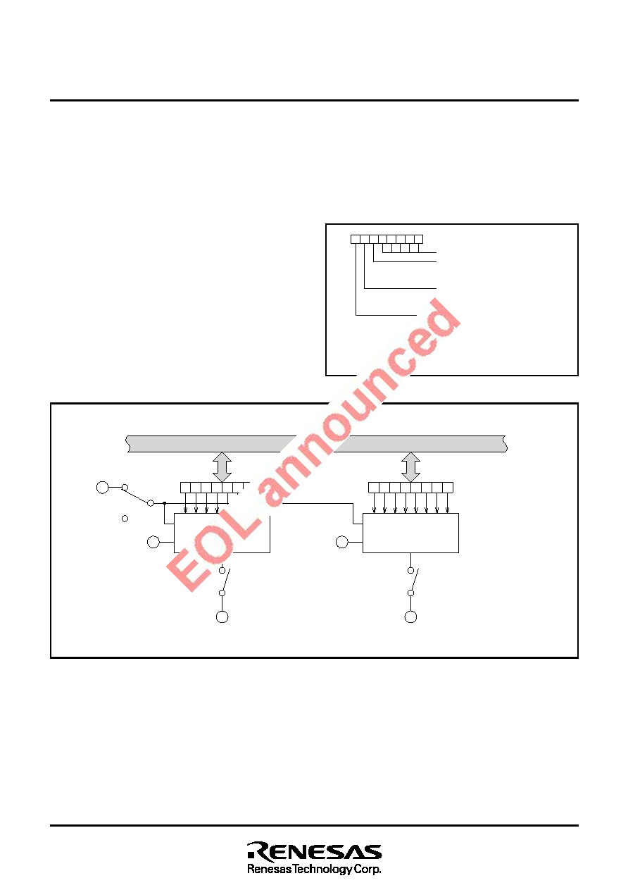
Fig. 72 D-A converter block diagram
D-A CONVERTER
The D-A converter is an 8-bit R-2R method D-A converter and con-
sists of two independent D-A converters. Figure 72 shows the block
diagram of the D-A converter and Figure 73 shows the bit configura-
tion of A-D control register 1.
D-A conversion is performed by writing a value in the corresponding
D-A register. The conversion result is output by bits 6 and 7 of A-D
control register 1 (address 1F16). When bit 7 is “1”, the conversion
result is output from DA0 pin.
When bit 6 is “1”, the conversion result is output from DA1pin.
The output analog voltage V is determined according to the value n
(“n” is a decimal number) set in the D-A register.
V = VREF
× n/256 (n = 0 to 255)
VREF : Reference voltage
The D-A output enable bit is cleared to “0” at reset. Whether to con-
nect the reference voltage input (VREF) with the ladder network or not
depends on bit 5 of the A-D control register 1. The VREF pin is con-
nected when bit 5 is “0” and is disconnected when bit 5 is “1” (High
impedance state).
Fig. 73 A-D control register 1 bit configuration
7
×××××
6543210
Not used for D-A converter
VREF connection select bit (Note)
0 : VREF is connected
1 : VREF is not connected
D-A1 output enable bit
0 : Disable output
1 : Enable output
D-A0 output enable bit
0 : Disable output
1 : Enable output
A-D control register 1
Address
1F16
When A-D or D-A conversion is not performed, current from the VREF
pin to the ladder network can be cut off by disconnecting ladder net-
work from the VREF pin.
Before starting A-D or D-A conversion, wait for 1
s or more after
clearing bit 5 to “0”. An external buffer must be connected when con-
necting to a low impedance load because there is no built-in D-A out-
put buffer.
Note : When the expansion function select bit (bit 5 of peripheral
function select register 1 ; refer to Fig. 62) is “1,” bit 5 can be
written and changed.
R-2R ladder network
D-A0 output
enable bit
D-A register 0
(Address 6816)
D-A0 pin
AVSS
R-2R ladder network
Data bus (even)
D-A1 output
enable bit
D-A register 1
(Address 6A16)
D-A1 pin
AVSS
VREF
VREF connection
select
相關(guān)PDF資料 |
PDF描述 |
|---|---|
| M37754S4CHP | 16-BIT, 40 MHz, MICROCONTROLLER, PQFP100 |
| M37902FCCHP | 16-BIT, FLASH, 26 MHz, MICROCONTROLLER, PQFP100 |
| M37902FGCHP | 16-BIT, FLASH, 26 MHz, MICROCONTROLLER, PQFP100 |
| M37906F8CSP | 16-BIT, FLASH, 20 MHz, MICROCONTROLLER, PDIP42 |
| M37906F8CFP | 16-BIT, FLASH, 20 MHz, MICROCONTROLLER, PDSO42 |
相關(guān)代理商/技術(shù)參數(shù) |
參數(shù)描述 |
|---|---|
| M37754S4CHP | 制造商:RENESAS 制造商全稱(chēng):Renesas Technology Corp 功能描述:SINGLE-CHIP 16-BIT CMOS MICROCOMPUTER |
| M3775PR-H400CL | 制造商:Bonitron 功能描述:OVERVOLTAGE BRAKING RESISTOR |
| M3775RK-0.75A | 制造商:Bonitron 功能描述:OVERVOLTAGE BRAKING RESISTOR |
| M3775RK-C0.50A | 制造商:Bonitron 功能描述:OVERVOLTAGE BRAKING RESISTOR |
| M3775RK-C0.50B | 制造商:Bonitron 功能描述:OVERVOLTAGE BRAKING RESISTOR |
發(fā)布緊急采購(gòu),3分鐘左右您將得到回復(fù)。