- 您現(xiàn)在的位置:買賣IC網(wǎng) > PDF目錄369884 > LXP710PE Ultraframer DS3/E3/DS2/E2/DS1/E1/DS0 PDF資料下載
參數(shù)資料
| 型號: | LXP710PE |
| 元件分類: | 通信及網(wǎng)絡 |
| 英文描述: | Ultraframer DS3/E3/DS2/E2/DS1/E1/DS0 |
| 中文描述: | Ultraframer DS3/E3/DS2/E2/DS1/E1/DS0 |
| 文件頁數(shù): | 53/84頁 |
| 文件大?。?/td> | 1108K |
| 代理商: | LXP710PE |
第1頁第2頁第3頁第4頁第5頁第6頁第7頁第8頁第9頁第10頁第11頁第12頁第13頁第14頁第15頁第16頁第17頁第18頁第19頁第20頁第21頁第22頁第23頁第24頁第25頁第26頁第27頁第28頁第29頁第30頁第31頁第32頁第33頁第34頁第35頁第36頁第37頁第38頁第39頁第40頁第41頁第42頁第43頁第44頁第45頁第46頁第47頁第48頁第49頁第50頁第51頁第52頁當前第53頁第54頁第55頁第56頁第57頁第58頁第59頁第60頁第61頁第62頁第63頁第64頁第65頁第66頁第67頁第68頁第69頁第70頁第71頁第72頁第73頁第74頁第75頁第76頁第77頁第78頁第79頁第80頁第81頁第82頁第83頁第84頁
HDSL Framer/Mapper for 1168 kbps Applications
—
LXP710
Datasheet
53
Loop 2 QRSS Test Pattern Error Counter (2 bytes)
Address: 5A
Abbreviation: L2PATECH
Read
Address: 5B
Abbreviation: L2PATECL
Read
Loop 2 Mux Restart Counter Register
Address: 5C
Abbreviation: MX2RSCNTR
Read
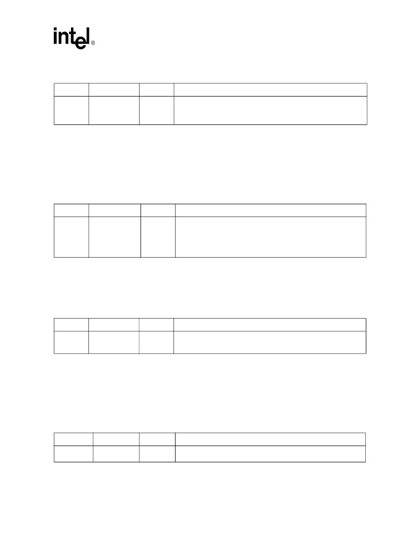
Table 83. Demux Loop 2 BPV Error Count
Bit
Name
Default
Description
<7:0>
BPV2EC<7:0>
0
Demux Loop 2 BPV Error Counter. This 8-bit counter increments each time
one or more errors are detected on the demux Loop 2 BPV bits. After a
microprocessor read, the counter is cleared. This counter is disabled when the
LOSW2 signal is High, and automatically stops at 0FFh to prevent overflow.
Table 84. Loop 2 QRSS Test Pattern Error Counter (High byte)
Bit
Name
Default
Description
<7:0>
PAT2EC<15:8>
0
Loop 2 Test Pattern Error Counter (High byte). This 16-bit counter increments
each time the demux test pattern receiver detects a pattern error. When the
upper byte is read, the current count of both bytes is latched and the counter
is cleared. This counter is disabled when pattern sync is lost. This counter
does not stop counting at 0FFFFh, however, a latched overflow status bit is
provided in the General Interrupt Vector Status register.
Table 85. Loop 2 QRSS Test Pattern Error Counter (Low byte)
Bit
Name
Default
Description
<7:0>
PAT2EC<7:0>
0
Loop 2 Test Pattern Error Counter (Low byte). The lower byte is latched when
the upper byte is read. Therefore, this byte must be read last when reading the
16-bit Pattern Error Counter.
Table 86. Loop 2 Mux Restart Counter
Bit
Name
Default
Description
<7:0>
n/a
0
Loop 2 mux restart counter. Increments each time the mux loop has been
restarted.
相關PDF資料 |
PDF描述 |
|---|---|
| LXP730LE | Ultraframer DS3/E3/DS2/E2/DS1/E1/DS0 |
| LXT1000 | LAN TRANSCEIVER|SINGLE|HYBRID|BGA|492PIN|PLASTIC |
| LXT19908 | Amplifier. Other |
| LXT300JE | PCM Transceiver |
| LXT300NE | PCM Transceiver |
相關代理商/技術參數(shù) |
參數(shù)描述 |
|---|---|
| LXP730 | 制造商:INTEL 制造商全稱:Intel Corporation 功能描述:Multi-Rate DSL Framer |
| LXP730LE | 制造商:未知廠家 制造商全稱:未知廠家 功能描述:FRAMER/FORMATTER|CMOS|QFP|64PIN|PLASTIC |
| LXP80 | 制造商:Johnson Components 功能描述: |
| LXPB2SA-50SB-Q | 制造商:SMC Corporation of America 功能描述:Actuator, electric, ball bushing |
| LXPH0000 | 制造商:Red Lion Controls 功能描述:ANNUNCIATOR LABELS, 1 LPAX LABEL: PH 制造商:Red Lion Controls 功能描述:1 LPAX LABEL PH |
發(fā)布緊急采購,3分鐘左右您將得到回復。